


This version is outdated by a newer approved version. This version (22 Sep 2016 20:53) is a draft.
Approvals: 0/1The Previously approved version (20 Sep 2016 17:19) is available.
This version (22 Sep 2016 20:53) is a draft.Approvals: 0/1The Previously approved version (20 Sep 2016 17:19) is available.
This is an old revision of the document!
Table of Contents
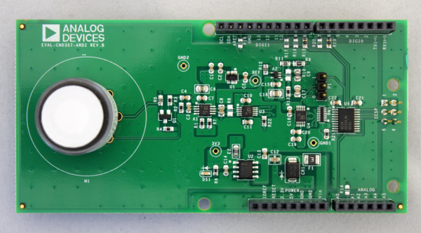
EVAL-CN0357-ARDZ Shield
CN0357 single-supply, low noise, portable gas detector circuit using an electrochemical sensor. The Alphasense CO-AX carbon monoxide sensor is used in this example. Electrochemical sensors offer several advantages for instruments that detect or measure the concentration of many toxic gases. Most sensors are gas specific and have usable resolutions under one part per million (ppm) of gas concentration.
The circuit shown in below uses the ADA4528-2, dual auto zero amplifier, which has a maximum offset voltage of 2.5 µV at room temperature and an industry leading 5.6 µV/√Hz of voltage noise density. In addition, the AD5270-20 programmable rheostat is used rather than a fixed transimpedance resistor, allowing for rapid prototyping of different gas sensor systems, without changing the bill of materials.
The ADR3412 precision, low noise, micropower reference establishes the 1.2 V common-mode, pseudo ground reference voltage with 0.1% accuracy and 8 ppm/°C drift.
For applications where measuring fractions of ppm gas concentration is important, using the ADA4528-2 and the ADR3412 makes the circuit performance suitable for interfacing with a 16-bit ADC, such as the AD7790.
Connectors and Jumper Configurations
PICTURE OF THE BOARD FILE with JUMPERS AND CONNECTORS HIGHLIGHTED
Sensor Footprint
NOTE - Three electrode electrochemical toxic gas sensors can be used with the EVAL-CN0357-ARDZ The footprint can accommodate 3 different sizes of sensors.
The Alphasense CO-AX electrochemical gas sensor was used during testing and programming.
Recommended PCB Sockets(for Alphasense Sensors)
- A Series Sensors - Mill-Max 0364-0-15-15-13-27-10-0
- B Series Sensors - Mill-Max 0294-0-15-15-06-27-10-0
- D Series Sensors - Mill-Max 0667-0-15-15-30-27-10-0
- The sensor may be connected to the M1 footprint using the appropriate pin sockets
Jumper P1 Settings
- “0” position - Sensor output connected to ADC(defualt)
- “1” position - Sensor output connected to A1 pin of ANALOG header, for connection to external ADCs
Chip Select
NEED CHIP select picture of header!!!
| AD7790_CS Pins (P??) | Arduino GPIO Pin (P??) |
|---|---|
| Pin 1 shunted to Pin 2 | GPIO 8 |
| Pin 3 shunted to Pin 4 | GPIO 9 |
| Pin 5 shunted to Pin 6 | GPIO 10 |
NEED CHIP select picture of header!!!
| AD5270_CS Pins (P??) | Arduino GPIO Pin (P??) |
|---|---|
| Pin 1 shunted to Pin 2 | GPIO 8 |
| Pin 3 shunted to Pin 4 | GPIO 9 |
| Pin 5 shunted to Pin 6 | GPIO 10 |
Schematic, Bill of Materials, Gerber Files, Layout Files
EVAL-CN0359-EB1Z Rev B Files
EVAL-CN0359-EB1Z Rev A Files
Change Log
RevB to RevC:
- U1 (from MCCOG128064A6S-SPTLY to BTHQ128064AVC1-COG-STF-LED)
- C32 (from 330n to NP)
- Software (conductivity result reliability routines removed)
- Software (setup and hold time setting added)
- Software (RS-485 communication routines added)
RevA to RevB:
- U1 (from MCCOG128064A6S-SPTLY to BTHQ128064AVC1-COG-STF-LED)
- C32 (from 330n to NP)
- Software (conductivity result reliability routines removed)
- Software (setup and hold time setting added)
- Software (RS-485 communication routines added)
Software
resources/eval/user-guides/eval-adicup360/hardware/cn0357.1474570400.txt.gz · Last modified: 22 Sep 2016 20:53 by Brandon Bushey