


This version is outdated by a newer approved version. This version (25 Mar 2021 02:44) was approved by Harvey John De Chavez.The Previously approved version (15 Mar 2021 05:18) is available.
This version (25 Mar 2021 02:44) was approved by Harvey John De Chavez.The Previously approved version (15 Mar 2021 05:18) is available.This is an old revision of the document!
Table of Contents
ADXRS290 Gyroscope PMOD Demo
The EVAL-ADXRS290-PMDZ is a simple Pmod form-factor evaluation board for the ADXRS290, a high-performance MEMS pitch-and-roll (dual-axis in-plane) angular rate sensor (gyroscope) designed for use in stabilization applications.

The solution senses and digitizes the X-axis and Y-axis (also called roll and pitch) angular rates, producing a positive reading for clockwise rotation about the x-axis and y-axis.

The ADXRS290 provides an output full-scale range of ±100°/s with a sensitivity of 200 LSB/°/s. Its resonating disk sensor structure enables angular rate measurement about the axes normal to the sides of the package around an in-plane axis. Angular rate data is formatted as a 16-bit two's complement and is accessible through an SPI digital interface. The ADXRS290 exhibits a low noise floor of 0.004°/s/√Hz and features programmable high-pass and lowpass filters.
The ADXRS290 communicates via 4-wire SPI and operates as a peripheral (slave) device, with a maximum clock frequency of 12MHz.

The Digital communication on the EVAL-ADXRS290-PMDZ is accomplished using a standard expanded SPI PMOD port.
| Connector P1 | |
|---|---|
| Description | Pin(s) |
| SS | 1 |
| MOSI | 2 |
| MISO | 3 |
| SCLK | 4 |
| GND | 5, 11 |
| IOVDD | 6, 12 |
| SYNC | 7 |
Features
- Pitch and roll rate gyroscope
- Ultralow noise: 0.004°/s/√Hz
- High vibration rejection over a wide frequency range
- Power saving standby mode
- 80 µA current consumption in standby mode
- Fast startup time from standby mode: <100 ms
- Low delay of <0.5 ms for a 30 Hz input at the widest bandwidth setting
- Serial peripheral interface (SPI) digital output
- Programmable high-pass and low-pass filters
- 2000 g powered acceleration survivability
- 2.7 V to 5.0 V operation
- −25°C to +85°C operation
- PMOD form factor
Device Driver Support
Two example device driver solutions are provided for controling the EVAL-ADXRS290-PMDZ PMOD using the no-OS device driver on the EVAL-ADICUP3029 platform and Linux device driver on the Raspberry Pi platform.
1. EVAL-ADICUP3029
- The ADICUP3029 example application uses the ADXRS290 no-OS driver, and emulates the Linux IIO framework through the tinyiiod daemon library. The application communicates with the host computer via the serial backend, over a USB-UART physical connection. This facilitates rapid application development on a host computer, independent from embedded code development.
2. Raspberry Pi
- The Linux driver uses the Industrial Input/Output (IIO) framework, greatly simplifying the development of applicaiton code via the cross-platform Libiio library, which is written in C and includes bindings for Python, MATLAB, C#, and other languages. Application code can run directly on the platform board, communicating with the device over the local bakend, or from a remote host over the network or USB backends.
Similarly, utility software (iio_info, IIO Oscilloscope, PyADI-IIO, etc.) can be used for both the EVAL-ADXRS290-PMDZ on Raspberry PI and on ADICUP3029.
General Setup Using ADICUP3029
The EVAL-ADXRS290-PMDZ can be used with ADICUP3029.
 Software Architecture
Demo Requirements
The following is a list of items needed in order to replicate this demo.
Hardware:
- EVAL-ADICUP3029
- EVAL-ADXRS290-PMDZ
- Mirco USB to USB cable
- PC or Laptop with a USB port
Software:
There are two basic ways to program the ADICUP3029 with the software for the CLI Demo.
- Dragging and Dropping the .Hex to the Daplink drive
- Building, Compiling, and Debugging using CCES
Using the drag and drop method, the software is going to be a version that Analog Devices creates for testing and evaluation purposes. This is the EASIEST way to get started with the reference design.
Importing the project into CrossCore is going to allow you to change parameters and customize the software to fit your needs, but will be a bit more advanced and will require you to download the CrossCore toolchain.
The software for the ADICUP3029_ADXRS290 demo can be found here:
Prebuilt ADXRS290_IIO Hex File
Complete ADXRS290_IIO Source Files
To build the project from source, follow the instructions in the no-os wiki.
Setting up the Hardware
- Connect EVAL-ADXRS290-PMDZ board at connector P8 of the EVAL-ADICUP3029.
- Connect a micro-USB cable to the P10 connector of the EVAL-ADICUP3029 and connect it to a computer. The final setup should look similar to the picture below.

Flashing the Firmware/Program

- Make sure the following switches are as shown from the table below:
- Connect the ADICuP3029 to the PC host via micro-USB cable as shown below.
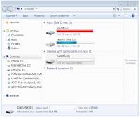
- From your PC, open My Computer and look for the DAPLINK drive, if you see this then the drivers are complete and correct.
- Simply extract the provided zip file. Do note that when you extract the zip file, there are two Hex file compressed inside. For this demo use the adxrs290-pmdz_aducm3029_iio_uart.hex. Then drag and drop this Hex file to the DAPLINK drive and your ADICUP3029 board will be programmed. The DS2 (red) LED will blink rapidly.
- The DS2 will stop blinking and will stay ON once the programming is done.

An alternative human-readable Command Line Interface (CLI) program is also available for the ADXRS290 Pmod on the EVAL-ADXRS290-PMDZ:
ADXRS290 Gyroscope PMOD Command Line Interface Demo
General Setup Using Raspberry Pi
The EVAL-ADXRS290-PMDZ can be used with a Raspberry Pi.
Demo Requirements
The following is a list of items needed in order to replicate this demo.
- Hardware
- EVAL-ADXRS290-PMDZ Circuit Evaluation Board
- Raspberry PI Zero, Zero W, 3B+, or 4
- 16GB (or larger) Class 10 (or faster) micro-SD card
- 5Vdc, 2.5A power supply with micro USB connector (USB-C power supply for Raspberry Pi 4)
- Electrical connection hardware (choose one):
- 12x 15cm socket-to-socket jumpers such as these from Schmartboard
- User interface setup (choose one):
- HDMI monitor, keyboard, mouse plugged directly into Raspberry Pi
- Host Windows/Linux/Mac computer on same network as Raspberry Pi
- Software
Loading Image on SD Card
In order to control the EVAL-ADXRS290-PMDZ from the Raspberry Pi, you will need to install ADI Kuiper Linux on an SD card. Complete instructions, including where to download the SD card image, how to write it to the SD card, and how to configure the system are provided at Analog Devices Kuiper Linux.
Write the image and follow the system configuration procedure.
Configuring the SD Card
Follow the Hardware Configuration procedure under Preparing the Image: Raspberry Pi in the Analog Devices Kuiper Linux page, substituting the following lines in config.txt:
dtoverlay=rpi-adxrs290
Setting up the Hardware
To set up the circuit for evaluation, consider the following steps:

Do note that the I/O pins of the Raspberry Pi board are only 3.3V tolerant. Any peripheral to be attached should be powered by a source not exceeding 3.3V.
- Connect EVAL-ADXRS290-PMDZ board at male header connector of the Raspberry Pi.
- Burn the SD card with the proper ADI Kuiper Linux image. Insert the burned SD card on the designated slot on the RPi.
- Connect the system to a monitor using an HDMI cable through the mini HDMI connector on the RPi.
- Connect a USB keyboard and mouse to the RPi through the USB ports.
- Power on the RPi board by plugging in a 5V power supply with a micro-USB connector. The final setup should look similar to the picture below.

Software (both ADICUP3029 and Raspberry Pi)
Connection
To be able to connect your device, the software must be able to create a context. The context creation in the software depends on the backend used to connect to the device as well as the platform where the EVAL-ADXRS290-PMDZ is attached. Two platforms are currently supported for the ADXRS290: Raspberry Pi using the ADI Kuiper Linux and the ADICUP3029 running the ADXRS290 IIO demo project. The user needs to supply a URI which will be used in the context creation.
The iio_info command is a part of the libIIO package that reports all IIO attributes. Make sure that you have the libIIO package installed on your machine. Upon installation, simply enter the command on the terminal line to access it.
For RPI Direct Local Access:
iio_info
For Windows machine connected to Raspberry Pi:
iio_info -u ip:<ip address of your ip>
Example:
- If your Raspberry Pi has the IP address 192.168.1.7, you have to use iio_info -u ip::192.168.1.7 as your URI
Do note that the Windows machine and the RPI board should be connected to the same network in order for the machine to detect the device.
For Windows machine connected to ADICUP3029:
iio_info -u serial:<serial port>
Examples:
- In a Windows machine, you can check the port of your ADICUP3029 via Device Manager in the Ports (COM & LPT) section. If your device is in COM4, you have to use iio_info -u serial:COM4 as your URI.
- In a Unix-based machine, you will see it under the /dev/ directory in this format “ttyUSBn”, where n is a number depending on how many serial USB devices attached. If you see that your device is ttyUSB0, you have to use serial:/dev/ttyUSB0 as your URI.
IIO Commands
There are different commands that can be used to manage the device being used. The iio_attr command reads and writes IIO attributes.
analog@analog:~$ iio_attr [OPTION]...
Example:
- To look at the context attributes, enter this code on the terminal:
analog@analog:~$ iio_attr -a -C
The iio_reg command reads or writes SPI or I2C registers in an IIO device. This is generally not needed for end applications, but can be useful in debugging drivers. Note that you need to specify a context using the -u qualifier when you are not directly accessing the device via RPI or when you are using the ADICUP3029 platform.
analog@analog:~$ iio_reg -u <context> <device> <register> [<value>]
Example:
- To to read the device ID (register = 0x02) of an ADXRS90 interfaced via RPI from a Windows machine, enter the following code on the terminal:
iio_reg -u ip:<ip address> adxrs290 0x02
IIO Oscilloscope
Make sure to download/update to the latest version of IIO-Oscilloscope found on this linkhttps://github.com/analogdevicesinc/iio-oscilloscope/releases
- Once done with the installation or an update of the latest IIO-Oscilloscope, open the application. The user needs to supply a URI which will be used in the context creation of the IIO Oscilloscope and the instructions can be seen from the previous section.
- Press refresh to display available IIO Devices, once adxrs290 appeared, press connect.

Debug Panel
Below is the Debug panel of ADXRS290 wherein you can directly access the attributes of the device.

DMM Panel
Access the DMM panel to see the instantaneous reading of the X and Y's angular velocities.

Waveform Panel
The Waveform panel, also known as the Capture window, displays the real-time waveform of ADXRS290's response.

The readings from the DMM panel will freeze upon activation of the real-time plot in the waveform panel i.e. the two panels are designed to be used separately and not simultaneously.
PyADI-IIO
PyADI-IIO is a python abstraction module for ADI hardware with IIO drivers to make them easier to use. This module provides device-specific APIs built on top of the current libIIO python bindings. These interfaces try to match the driver naming as much as possible without the need to understand the complexities of libIIO and IIO.
Install PyADI-IIO using one of the methods in PyADI-IIO.
The ADXRS290 example requires a number of packages to be installed before it can be used. To ensure that all required packages are present, we will be installing them in a virtual environment so that other python projects will not be affected by this added configuration. Make sure that virtualenv has been installed before proceeding.
Creating a Virtual Environment
- Open a command prompt and navigate to the pyadi-iio directory.
- Create a virtual environment by entering the following command:
D:\pyadi-iio>python -m venv adxrs290
Note that the last argument adxrs290 is just the name of the virtual environment to be created. It can be replaced by any other name or identifier that you prefer. In case the code above does not work, try:
D:\pyadi-iio>virtualenv adxrs290
- Input the following command to activate the virtual environment:
D:\pyadi-iio>adxrs290\Scripts\activate
Installing the Packages
Upon activation of the virtual environment, enter the following commands:
(adxrs290) D:\pyadi-iio>pip install -r requirements.txt
(adxrs290) D:\pyadi-iio>pip install -r examples/requirements_adiplot.txt
(adxrs290) D:\pyadi-iio>python setup.py install
One of the packages in requirements_adiplot.txt is the PyQt5. If you already have a pre-installed PyQt5 prior to the installation of the packages, we suggest that you uninstall the said package in the virtual environment. Duplicate installations may sometimes cause errors that inhibit the system from displaying the real-time plot. This can easily be done by inputting the command: pip uninstall PyQt5 while the virtual environment is active.
Running the Example
- Connect the ADXRS290 to the device platform you've chosen.
- If interfaced via RPI, connect your laptop to the same network as the ADXRS290 and take note of its IP address. For ADICUP3029, take note of the serial port used.
- On the source code, go to the examples folder and open adxrs290.py. Provide the necessary context in order to detect the device. Make sure that only one context source is active and the other one is commented out depending on whether you are using the RPI board or the ADICUP3029.
- Run the example by typing this line on the command prompt:
D:\pyadi-iio\examples>python adxrs290.py
Below is a copy of the python script:
adxrs290.pyIt will return these lines of data on the terminal:

- You can opt to see a real-time plot of ADXRS290's output. To do this, open adxrs290.py and set enable_plot to True.
 A plot will pop-up after running the code:


Video Guides
Unboxing
Schematic, PCB Layout, Bill of Materials
Additional Information and Useful Links
Reference Demos & Software
resources/eval/user-guides/circuits-from-the-lab/eval-adxrs290-pmdz.1616636666.txt.gz · Last modified: 25 Mar 2021 02:44 by Harvey John De Chavez