


This version is outdated by a newer approved version. This version (09 Jan 2021 00:36) was approved by Robin Getz.The Previously approved version (04 May 2019 20:00) is available.
This version (09 Jan 2021 00:36) was approved by Robin Getz.The Previously approved version (04 May 2019 20:00) is available.This is an old revision of the document!
Table of Contents
Production testing of the AD-FMCDAQ2 / AD-FMCDAQ3
Overview
The production testing is quite simple. Since each board has been completely characterized, and we know the layout is good, we can just look for gross errors.
There are multiple test files for the different boards. (all in github).
- AD-FMCDAQ2_test.ini : used to test AD-FMCDAQ2-EBZ
- AD-FMCDAQ3_test.ini : used to test AD-FMCDAQ3-EBZ
The tests and test parameters are in in the ./iio-oscilloscope/profiles/AD-FMCDAQ2_test.ini file. This is broken down into the following sections:
Temperature
<source master/profiles/AD-FMCDAQ2_test.ini:/temp/-/^$/ shell iio-oscilloscope>
The ad7291.in_temp0_raw is the raw results from the AD7291 - which is 0.25°C. 80 refers to 80 steps of 0.25°C or 20°C, and 160 refers to 40°C. This allows the tests to be done in a normal lab setting.
Voltage
<source master/profiles/AD-FMCDAQ2_test.ini:/tolerances/-2/^$/ shell iio-oscilloscope>
This section requires checking the schematics. Specifically, sheet 7 shows how the AD7291 is connected. 1% resistors connect various voltages, and things are divided down to ensure that the voltage levels don't exceed full scale.
The explanation of how the valid ranges are calculated is similar to the same tests for the FMComms boards.
Signals
<source master/profiles/AD-FMCDAQ2_test.ini:/Ignore/-15/^$/ shell iio-oscilloscope>
First the noise floor is checked when no input is supplied to make sure it is within a certain threshold. Then tones of approximately 97 MHz, 185 MHz, and 233 MHz are input against each channel individually and the fundamental frequency as well as the 2nd through 7th harmonics are checked to make sure they are within set bounds.
Creating an SD test card
First, write the latest available SD card image found at https://wiki.analog.com/resources/tools-software/linux-software/zynq_images to a spare card and prepare the card to boot into Linux as detailed on that page for the target FMCOMMS and carrier boards (copy the right BOOT.BIN and devicetree.dtb files into the base directory of the SD card's boot partition).
Then the card needs to be modified to run the tests automatically on boot. Test scripts are provided in https://github.com/analogdevicesinc/linux_image_ADI-scripts that automate initializing osc with the correct profile and environment.
Note that different boards use different tests scripts as seen in the following mapping:
- test_fmcdaq2.sh : used to test AD-FMCDAQ2-EBZ
- test_fmcdaq3.sh : used to test AD-FMCDAQ3-EBZ
Select the correct script above for target test setup and alter the launcher for osc to run that test script instead of a regular osc instance(/home/analog/.config/autostart). See the following example diff for required changes to the launcher to run the FMCDAQ2/3 tests on boot:
--- a/osc.desktop
+++ b/osc.desktop
@@ -1,5 +1,5 @@

 [Desktop Entry]
-Exec=gksudo -u root /usr/local/bin/osc
+Exec=sudo /usr/local/bin/test_fmcdaq2.sh
 Icon=adi-osc
 Terminal=false
 Type=Application
 Categories=Science
 Name=ADI IIO Oscilloscope
 GenericName=ADI IIO Oscilloscope
Required hardware
- Zynq ZC706 REV 1.2
- FMCDAQ2/3 card
- RF loopback cables (2x)
- External monitor connected to the carrier via HDMI
- Keyboard and mouse (with USB hub if they aren't part of a combo device)
- USB OTG adapter
- DAQ2 test SD Card
- Ethernet cable
Required setup
- Plug in the external monitor and connect it via HDMI to the carrier board on P1.
- Connect the USB OTG adapter (and USB hub if needed) to the USB port on the carrier, then plug in the keyboard and mouse as well.
- Plug in the carrier board, insert the SD card for running the tests, and confirm that the carrier board is set to boot from SD (TODO: insert image).
- Attach the carrier board via the Ethernet cable to a network connection with Internet accessibility (used for time syncing).
Test process
- Attach the RF loopback cables to the card. See the images at the bottom of the page for correct placement.
- Plug the card into the carrier board at the FMC HPC J37.
- Power on the carrier board.
- When prompted with the following message click OK

- When prompted with a window similar to the following image, enter the serial number found on the board and select the correct EEPROM file to write to the card.

- When prompted with the following message click OK

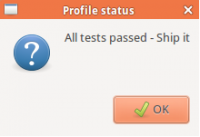
- When tests pass, the following window should be shown
 and if tests fail, a window similar to the following image should be shown
  In either case, hit the OK button to halt Linux and after several seconds power off the carrier board via the physical switch.
 - Remove the DAQ2/3 card and place the heatsink according to the pictures below
- Return to step 1 to continue with the next board.


| Cable placement | ||
|---|---|---|
 |  | |
| FMCDAQ2 | FMCDAQ3 | |
| Heatsink placement | ||
|---|---|---|
 |  |  |
| FMCDAQ2 | FMCDAQ3 top | FMCDAQ3 bottom |
resources/eval/user-guides/ad-fmcdaq2-ebz/testing.1610148766.txt.gz · Last modified: 09 Jan 2021 00:32 by Robin Getz