| Name | Format [int/dec] - [control/audio] | Function Description |
|---|---|---|
| Pin 0: Input Signal | dec - audio | Input Signal to monitor |
| Name | Format [int/dec] - [control/audio] | Function Description |
|---|---|---|
| Pin 0: Pulse Output | decimal - control | Pulse output in 5.23 format |
| GUI Control Name | Default Value | Range | Function Description |
|---|---|---|---|
| Value Threshold | 0 | -15, 15 | This is the threshold value that the input signal is compared to. |
| GUI Control Name | Compiler Name | Function Description |
|---|---|---|
| Value Threshold | CrossValueCrossAlg1 | When the value threshold is changed, it is written directly to the DSP |
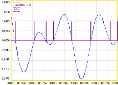
The Input signal is compared to the Value Threshold. Each time the input signal crosses this value (whether rising or falling) the output of the cell goes high. Otherwise the output of the cell is low. Below is a sample of the algorithm doing zero-cross detection, which is the default state of the block.

In some applications it is useful not just to know when there is a value cross, but also count the number of times that this happens during a specified time. Using the Value-Cross Detection block along with the Pulse Counter, allows the number of value-crosses to be counted. The following image uses a sine tone input, on/off switches, Pulse Counter, Readback cell, and GPIO output.

| Toolbox Path | Basic DSP - Logic - Value Cross Detection |
| Cores Supported | AD1940 ADAU170x ADAU144x ADAU176x ADAU178x |
| “Grow Algorithm” Supported | no |
| “Add Algorithm” Supported | yes - see Algorithm Addition Information |
| Subroutine/Loop Based | no |
| Program RAM | 15* |
| Data RAM | 3* |
| Parameter RAM | 1* |
*Numbers are based on one instance of the algorithm with no additional “add”