


This version is outdated by a newer approved version. This version (19 May 2020 10:15) is a draft.
Approvals: 0/1
This version (19 May 2020 10:15) is a draft.Approvals: 0/1
This is an old revision of the document!
Table of Contents
Sigma Delta ADC Temperature-BLE Demo
Introduction
This page gives an overview of using the Analog Devices Sigma Delta ADCs with Cortex-M3 ARM processor based ADuCM3029 Cog Eval Board. The intended demo application shows how to convert an external sensor data into actual units and transmit them over either Bluetooth or UART link using ADIs ADuCM3029 Cog board and Bluetooth Eval board. The operation can be better illustrated using below diagram.

Interface Overview
1) Temperature Sensing using Sigma Delta ADCs
The below diagram shows the temperature sensing scheme using AD7124 Sigma Delta ADC. It uses T-Type thermocouple and 2-wire RTD sensors as an external analog inputs. The Thermocouple acts as a hot junction and RTD as a cold junction compensation. This combination provides a precise measurements of ambient temperature over a very wide range.

AD7124 Eval board has default on-board KTY-81/110 RTD sensor (silicon Thermistor) connected between analog inputs AIN4 and AIN5. However, for the complete RTD measurement, the precision resistor (Rref) needs to be connectd externally along with Rhead headroom resistor. Rref needs to have 0.1% precision for complete accuracy. The choice of this reference resistor depends upon the Ref output voltage and excitation current. Use below application note for more details on the temperature sensing using RTD:
RTD Measurement System Using a Precision Sigma-Delta ADC
Thermocouple needs to be connected externally between analog inputs AIN2 and AIN3. Use below application note for more details on the temperature sensing using Thermocouple:
Thermocouple Measurement System Using a Precision Sigma-Delta ADC
For temperature sensing using AD7124 Eval board and ADuCM3029 COG board please use below software and hardware configuration:
T-Type Thermocouple (Chn0):
- AINP: AIN2, AINM: AIN3
- PGA Gain: 128
- Internal Vref Enabled
- Vbias enabled on AIN3
RTD Thermistor (Chn1):
- AINP: AIN4, AINM: AIN5
- PGA Gain: 8
- REFIN1+ and REFIN1- Enabled
- Excitation current set to 100uA on AIN2 (Iout0) pin
- Precision Reference: 22 Kohm and Rheadroom: 250 Ohm
Other Jumper Setting:
- LK3, LK4 and LK5 Removed
- LK6 both inserted
The above mentioned parameters are for AD7124 Eval board and associated sensing circuitry. The same parameters are configured in the firmware application as well. For other ADC Eval Boards, please use proper combination of these parameters based on your design, both in hardware and in software.
2) Interfacing ADuCM3029 Cog Board with Sigma Delta ADCs/Eval Board
The ADuCM3029 COG board is connected to Sigma Delta ADC Eval board using a Gear Expander board. Depending upon the digital interface used on Sigma Delta ADCs, the connection could be either 4 line SPI or 3 line I2C. The connection can be done either using SDP breakout board or by directly soldering fly wires from the ADC Evaluation board to ADuCM3029 Expander Gear board. The sample connection for the AD7124 Eval board with COG board is shown below using a fly wires. The wires are directly soldered on the Eval board, but for better connection, use the SDP breakout board:


The above hardware connection is for AD7124 Eval board and ADuCM3029 COG. For other ADC Eval Boards, please refer respective Eval board manual for digital interface connection details.
3) Interfacing ADuCM3029 Cog Board with Bluetooth Eval Board
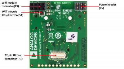
The below diagrams shows the connection between ADuCM3029 COG Board and Bluetooth Eval board. There are no additional jumper settings needed. Please refer user manual for more details on the hardware connection:
Primary-side

Secondary-side
Firmware Overview
Downloads
Latest firmware (Use below link):
Development Tools
The firmware uses Analog Devices Cross Core Embedded Studio (CCES) as a development IDE, with in-built ARM GCC compiler. To use CCES for ARM based projects, use below wiki page:
https://wiki.analog.com/resources/eval/user-guides/eval-adicup3029/tools/cces_user_guide
Code Structure

Using the Firmware
The entry point to firmware is defined in main.cpp file (a main function). This function is responsible for initializing and configuring the system peripherals. This module is also responsible for getting the sensor data from sampling engines and dispatch it over either Low Energy Bluetooth Link Or UART link.
The selection b/w UART or Bluetooth can be done by commenting/uncommenting below macro:
/* Select communication mode. Comment below to select UART as default com mode */
//#define ADI_BLUETOOTH_COMM
The following sensors are used in the firmware and data from them is dispatched over UART/Bluetooth Link:
- Thermocouple + RTD (Temperature Sensor interfaced with Sigma Delta ADC e.g AD7124)
- ADT7420 (ADuCM3029 COG On-Board Temperature Sensor)
- ADXL362 (ADuCM3029 COG On-Board Accelerometer Sensor)
resources/tools-software/product-support-software/sigma-delta_adc_temperature-ble_demo.1589876125.txt.gz · Last modified: 19 May 2020 10:15 by Mahesh Phalke