


This version (14 Jan 2021 05:44) was approved by Robin Getz.The Previously approved version (03 Jan 2021 21:46) is available.
Table of Contents
Sigma Delta ADC Temperature-BLE Demo
Introduction
This page gives an overview of using the Analog Devices Sigma Delta ADCs with Cortex-M3 ARM processor based ADuCM3029 Cog Eval Board. The intended demo application shows how to convert an external sensor data into actual units and transmit them over either Bluetooth or UART link using ADIs ADuCM3029 Cog board and Bluetooth Eval board. The operation can be better illustrated using below diagram.

Interface Overview
1) Temperature Sensing using Sigma Delta ADCs
The below diagram shows the temperature sensing scheme using AD7124 Sigma Delta ADC. It uses T-Type thermocouple and 2-wire RTD sensors as an external analog inputs. The Thermocouple acts as a hot junction and RTD as a cold junction compensation. This combination provides a precise measurements of ambient temperature over a very wide range.

AD7124 Eval board has default on-board KTY-81/110 RTD sensor (silicon Thermistor) connected between analog inputs AIN4 and AIN5. However, for the complete RTD measurement, the precision resistor (Rref) needs to be connectd externally along with Rhead headroom resistor. Rref needs to have 0.1% precision for complete accuracy. The choice of this reference resistor depends upon the Ref output voltage and excitation current. Use below application note for more details on the temperature sensing using RTD:
RTD Measurement System Using a Precision Sigma-Delta ADC
Thermocouple needs to be connected externally between analog inputs AIN2 and AIN3. Use below application note for more details on the temperature sensing using Thermocouple:
Thermocouple Measurement System Using a Precision Sigma-Delta ADC
For temperature sensing using AD7124 Eval board and ADuCM3029 COG board please use below software and hardware configuration:
T-Type Thermocouple (Chn0):
- AINP: AIN2, AINM: AIN3
- PGA Gain: 128
- Internal Vref Enabled
- Vbias enabled on AIN3
RTD Thermistor (Chn1):
- AINP: AIN4, AINM: AIN5
- PGA Gain: 8
- REFIN1+ and REFIN1- Enabled
- Excitation current set to 100uA on AIN2 (Iout0) pin
- Precision Reference: 22 Kohm and Rheadroom: 250 Ohm
Other Jumper Setting:
- LK3, LK4 and LK5 Removed
- LK6 both inserted
The above mentioned parameters are for AD7124 Eval board and associated sensing circuitry. The same parameters are configured in the firmware application as well. For other ADC Eval Boards, please use proper combination of these parameters based on your design, both in hardware and in software.
2) Interfacing ADuCM3029 Cog Board with Sigma Delta ADCs/Eval Board
The ADuCM3029 COG board is connected to Sigma Delta ADC Eval board using a Gear Expander board. Depending upon the digital interface used on Sigma Delta ADCs, the connection could be either 4 line SPI or 3 line I2C. The connection can be done either using SDP breakout board or by directly soldering fly wires from the ADC Evaluation board to ADuCM3029 Expander Gear board. The sample connection for the AD7124 Eval board with COG board is shown below using a fly wires. The wires are directly soldered on the Eval board, but for better connection, use the SDP breakout board:


The above hardware connection is for AD7124 Eval board and ADuCM3029 COG. For other ADC Eval Boards, please refer respective Eval board manual for digital interface connection details.
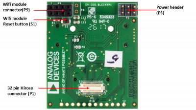
3) Interfacing ADuCM3029 Cog Board with Bluetooth Eval Board
The below diagrams shows the connection between ADuCM3029 COG Board and Bluetooth Eval board. There are no additional jumper settings needed. Please refer user manual for more details on the hardware connection:
Primary-side

Secondary-side
4) Leveraging ADuCM3029 Cog On-Board Peripherals
In addition to Sigmal Delta ADC interface and Bluetooth interface, the ADuCM3029 has number of on-board peripherals, including ADT7420 Temperature sensor, ADXL362 Accelerometer, Push buttons and LEDs, SD Card, Wi-Fi/RF interface, etc. The firmware interface with ADT7420 temperature sensor and ADXL362 accelerometer to transmit sensor data. Also, it uses Push button PB1 to come out of Hibernate mode, which is tied to External Interrupt 1 pin. The ADXL362 interrupt ativity pin is tied to external interrupt 2. Both these interrupts are used by MCU to come out of hibernate mode. The PB2 is used to select the next sensor scanning and must be pressed when MCU is awake. This can be done by pressing PB1 first and them immediately PB2, which will first take MCU out of hibernate mode and then will select next sensor for sampling.
Firmware Overview
Downloads
Latest firmware (Use below link):
Development Tools
The firmware uses Analog Devices Cross Core Embedded Studio (CCES) as a development IDE, with in-built ARM GCC compiler. To develop CCES ARM based project, follow below wiki page guidelines:
https://wiki.analog.com/resources/eval/user-guides/eval-adicup3029/tools/cces_user_guide
Code Structure

The tempsensor project is compiled externally to BLE demo firmware project. The “libtempsensors.a” library file generated by this project is used during linking time in “sd-adc_cces_temperature-to-ble” project. So, when compiling the project, both these project must be present in same workspace.

Using the Firmware
Device Linker File Configuration (ADuCM3029.ld)
Because of the hibernate mode implementation, the device linker file has been modified to map the .data and .bss sections of memory to Bank0 and Bank1 of SRAM. The MCU in hibernate does not retain the contents of upper 16Kbytes of SRAM (Bank 3,4 and 5). Hence to avoid loosing data, it is necessary to map the data and bss sections to DSRAM_A in linker configuration file.
*Note: This has already been done in the distributed firmware. In case, you are not using hibernate mode, you can revert it back to DSRAM_B (the default one).
.data : AT (__etext)
{
.
.
} > DSRAM_A

.bss :
{
.
.
} > DSRAM_A
CMSIS Compatibility (startup_ADuCM3029.c)
The ADuCM3029 software package startup file is not yet updated to support latest changes in the ARM CMSIS drivers (CMSIS-CORE (M) Version 5.3.0 and above) and it creates conflicts in the startup_ADuCM3029.c file for duplicate identifiers. To avoid this conflict, startup file is modified as below:
#if __CM_CMSIS_VERSION < 0x050003
// For CMSIS-CORE(M) version 5.3.0 above, the below variables have defined
// with different data types in cmsis_gcc.h file from the device CMSIS pack.
// The ADuCM3029 start-up code is not yet up-to-date with the latest changes from
// the CMSIS pack. Hence commenting below code to avoid compilation errors.
extern uint32_t __copy_table_start__;
extern uint32_t __copy_table_end__;
extern uint32_t __zero_table_start__;
extern uint32_t __zero_table_end__;
#endif
main.cpp
The entry point to firmware is defined in main.cpp file (a main function). This function is responsible for initializing and configuring the system peripherals. This module is also responsible for getting the sensor data from sampling engines and dispatch it over Low Energy Bluetooth Link or/and UART link.
The selection b/w UART or Bluetooth dispatcher service can be done by commenting/uncommenting below macro. The UART link is also used to log the debug messages and so even with Bluetooth dispatcher service, you should be able to see all debug and sensor data messages on UART link.
/* Select communication mode. Comment below to select UART as default com mode */
//#define ADI_BLUETOOTH_COMM
The following sensors are used in the firmware and data from them is dispatched over UART/Bluetooth Link:
- Thermocouple + RTD (Temperature Sensor interfaced with Sigma Delta ADC e.g AD7124)
- ADT7420 (ADuCM3029 COG On-Board Temperature Sensor)
- ADXL362 (ADuCM3029 COG On-Board Accelerometer Sensor)
The processor is put into hibernate sleep mode after every frame transmission for 10sec timeout period. This is handled in main.cpp module as below:
/*
 * This puts the processor into hibernation mode, waiting for interrupts
 * The following interrupts can can wake the processor
 * 	BTN1 - user initiates sample
 * 	Axl  - acceleration threshold exceeded, triggers a Sample and transmit data
 *   	RTC  - Sample and transmit data on a periodic basic
 *
 * Before entering into hibernate mode, all the used peripherals must be
 * disable. Once the hibernate mode is exited by one of the above mentioned
 * interrupts, the peripherals which were disabled before, must be enabled again.
 *
 * In addition to that, when device exits from hibernate mode, by default
 * only the Bank0/Bank1 of data SRAM is retained. Therefore it is required
 * to map .data and .bss sections of memory to Bank0/1 of SDRAM in the device
 * linker file of the project (ADuCM3029.ld), so that data is retained when
 * controller comes out of hibernate mode.
 */
/* Perform the operations needed before entering into hibernate mode */
do_pre_hibernate_entry_operations();

/* enter full hibernate mode with no wakeup flag (always go back to sleep) and no masking */
if (adi_pwr_EnterLowPowerMode(ADI_PWR_MODE_HIBERNATE, &iHibernateExitFlag, 0)) {
	DEBUG_MESSAGE("System Entering to Low Power Mode failed");
}

/* Perform the operations needed after exit from hibernate mode */
do_post_hibernate_exit_operations();
app_config.h
This file allows user to select active Sigma Delta ADC that is used for external temperature sensing:
// **** Note for User: Active Device selection ****
// Select the device type from the list of below device type defines
// e.g. #define DEV_AD7124 -> This will make AD7124 as an Active Device.
// The Active Device is default set to AD7124, if device type is not defined.

#if defined DEV_AD7124
#define ACTIVE_DEVICE ID_AD7124
#else
#warning "No active device defined. AD7124 selected as default device"
#define DEV_AD7124
#define ACTIVE_DEVICE ID_AD7124
#endif
Dispatching Data Over Bluetooth/UART Link
The Bluetooth sensor data can be captured using a Analog Devices IoT node smart IOS application (for IOS/apple based devices). The application can be downloaded from below link:
https://apps.apple.com/us/app/iotnode/id1242751625#?platform=iphone
The more information about the bluetooth packet format is provided below:
https://wiki.analog.com/resources/eval/user-guides/eval-adicup3029/smart_app/ble_connect

For observing data using UART link using serial terminal (e.g. Tera Term), use below serial settings:
- Baud rate: 115200
- Data bits: 8-bits
- Parity: None
- Stop bits: 1

This page might not cover the all minute details of hardware/software configuration and operation. All the necessary links for the associated documents are provided above. Feel free to consult Analog Devices Engineer-Zone for feature requests, feedback, bug-reports etc.
resources/tools-software/product-support-software/sigma-delta_adc_temperature-ble_demo.txt · Last modified: 14 Jan 2021 05:38 by Robin Getz