 This version (01 Apr 2022 10:17) is a draft.
This is an old revision of the document!
The PMOD compatible evaluation/prototyping board is a small form factor, low cost, low noise, and low drift, 3-axis accelerometer sensor measurement board.
SPI PMOD peripheral connectors can be found on many 3rd party MCU or FPGA development boards, where the EVAL-ADXL355-PMDZ can be connected directly into those systems.

The ADXL355 PMOD board has to be supplied with 3.3V power. If using directly with a PMOD connector, the host board should be capable of providing the 3.3V supply.
The PMOD interface is a series of standardized digital interfaces for various digital communication protocols such as SPI, I2C, and UART. These interface types were standardized by Digilent, which is now a division of National Instruments. Complete details on the PMOD specification can be found here.
The specific interface used for the EVAL-ADXL355-PMDZ boards is the extended SPI. In general ADI has adopted the extended SPI connector for all PMOD devices which have an SPI interface. It provides flexibility to add interrupts, general purpose I/O, resets, and other important digitally controlled functions.
| P1 Pin Number | Pin Function | Mnemonic |
|---|---|---|
| Pin 1 | Chip Select | CS |
| Pin 2 | Master Out Slave In | MOSI |
| Pin 3 | Master In Slave Out | MISO |
| Pin 4 | Serial Clock | SCLK |
| Pin 5 | Digital Ground | DGND |
| Pin 6 | Digital Power | VDD |
| Pin 7 | Interrupt 1 | INT1 |
| Pin 8 | Not Connected | NC |
| Pin 9 | Interrupt 2 | INT2 |
| Pin 10 | Data Ready | DRDY |
| Pin 11 | Digital Ground | DGND |
| Pin 12 | Digital Power | VDD |
The goal of ADI Microcontroller No-OS is to be able to provide reference projects for lower end processors, which can't run Linux, or aren't running a specific operating system, to help those customers using microcontrollers with ADI parts. ADI No-OS offers generic drivers which can be used as a base for any microcontroller platform and also example projects which are using these drivers on various microcontroller platforms.
For more information about ADI No-OS and supported microcontroller platforms see: ADI No-OS
Information about the ADXL355 driver can be found here: ADXL355 driver
The SDP-K1, does not have a PMOD interface, but you may use Dupont male-female cables to make the required connections. The following tale shows how the connection between EVAL-ADXL355-PMDZ and SDP-K1 is realized in this project example.
| P1 EVAL-ADXL355-PMDZ Pin Number | SDP-K1 Pin Number | Function | Mnemonic |
|---|---|---|---|
| Pin 1 | DIGITAL 10 | Chip Select | CS |
| Pin 2 | DIGITAL 11 | Master Out Slave In | MOSI |
| Pin 3 | DIGITAL 12 | Master In Slave Out | MISO |
| Pin 4 | DIGITAL 13 | Serial Clock | SCLK |
| Pin 5 | DIGITAL GND | Digital Ground | DGND |
| Pin 6 | POWER 3.3V | Digital Power | VDD |
| Pin 10 | ANALOG IN A0 | Data Ready | DRDY |
Make sure that the VIO_ADJUST is set to 3.3V on SDP-K1.
Clone NO-OS with the --recursive flag:
git clone --recursive https://github.com/analogdevicesinc/no-OS
If however you've already cloned NO-OS without the --recursive flag, you may initialize all the submodules in an existing NO-OS clone with:
git submodule update --recursive --init
Please follow the steps below for No-OS Setup based on the environment you are using. Make sure you use the information for the specific platform you are using (e.g. STM32, MAXIM).
Prior to building a no-OS project, it is required to set up some environment variables so that the build process may find the necessary tools (compiler, linker, SDK etc.).
Use the following commands to prepare your environment for building no-OS projects:
The path of the project is no-OS/projects/eval-adxl355-pmdz/
Go in the project directory that should be built.
The build process creates a build directory in the project folder:
build
├── app
├── bsp
├── obj
├── project_name.elf
└── tmp
Once the .elf, .hex or .bin file has been generated, make sure the board is powered on, JTAG cable connected and use the following commands to upload the program to the board or debug.
Uploading the binary to target is generically achieved with:
$ make run
Use the following command to launch the SDK associated to the used platform in order to be able to debug graphically by clicking the debug button:
$ make sdkopen
Fore more details about the available make rules, check out this page.
The simple project contains the generic HAL initialization of the used platform, together with the SPI and UART driver configuration and initialization.
The SPI driver is used to communicate with the EVAL-ADXL355-PMDZ device, while the UART driver is used to display on the host machine the measured data.
The simple project contains the ADXL355 driver initialization in SPI mode:
struct adxl355_dev *adxl355;
struct adxl355_init_param init_data_adxl355 = {
	.comm_init.spi_init = sip,
	.comm_type = ADXL355_SPI_COMM,
};
ret = adxl355_init(&adxl355, init_data_adxl355);
if (ret < 0)
	goto error;
Some APIs are called in order to configure the ADXL355 device, after the initialization is performed. First of all, a soft reset is performed such that the device is put in a known state.
ret = adxl355_soft_reset(adxl355);
if (ret < 0)
	goto error;
After this, the sampling frequency and the operation mode is selected such that temperature measurements are also available.
// Set sampling frequency
ret = adxl355_set_odr_lpf(adxl355, ADXL355_ODR_3_906HZ);
if (ret < 0)
	goto error;

// Set operation mode
ret = adxl355_set_op_mode(adxl355, ADXL355_MEAS_TEMP_ON_DRDY_OFF);
if (ret < 0)
	goto error;
At this point the device is already performing measurements which are accessed continuously in a while loop at each second.
while(1) {
	pr_info("Single read \n");
        // Perform a single acceleration data read on all 3 axis from the device
	ret = adxl355_get_xyz(adxl355,&x[0], &y[0], &z[0]);
	if (ret < 0)
		goto error;
        // Print the obtained data
	pr_info(" x=%d"".%09u", (int)x[0].integer, (abs)(x[0].fractional));
	pr_info(" y=%d"".%09u", (int)y[0].integer, (abs)(y[0].fractional));
	pr_info(" z=%d"".%09u \n", (int)z[0].integer,(abs)(z[0].fractional));

        // Perform a FIFO reading (will read all the available data in the FIFO)
	ret = adxl355_get_fifo_data(adxl355, &fifo_entries, &x[0], &y[0], &z[0]);
	if (ret < 0)
		goto error;
        // Print the number of read entries from the FIFO
	pr_info("Number of read entries from the FIFO %d \n", fifo_entries);
        // Print the number of read data set from the FIFO
        // A data set contains acceleration measurements on all 3 axis
	pr_info("Number of read data sets from the FIFO %d \n", fifo_entries/3);
        // Print all the available data sets
	for (uint8_t idx = 0; idx < 32; idx ++) {
		if (idx < fifo_entries/3) {
			pr_info(" x=%d"".%09u m/s^2", (int)x[idx].integer, (abs)(x[idx].fractional));
			pr_info(" y=%d"".%09u m/s^2", (int)y[idx].integer, (abs)(y[idx].fractional));
			pr_info(" z=%d"".%09u m/s^2", (int)z[idx].integer, (abs)(z[idx].fractional));
			pr_info("\n");
		}
	}

	pr_info("==========================================================\n");
        // Read status register of the ADXL355 device
	ret = adxl355_get_sts_reg(adxl355, &status_flags);
	if (ret < 0)
		goto error;
        // Print status register information
	pr_info("Activity flag = %d \n", (uint8_t)(status_flags.fields.Activity));
	pr_info("DATA_RDY flag = %d \n", (uint8_t)(status_flags.fields.DATA_RDY));
	pr_info("FIFO_FULL flag = %d \n", (uint8_t)(status_flags.fields.FIFO_FULL));
	pr_info("FIFO_OVR flag = %d \n", (uint8_t)(status_flags.fields.FIFO_OVR));
	pr_info("NVM_BUSY flag = %d \n", (uint8_t)(status_flags.fields.NVM_BUSY));
	pr_info("===========================================================\n");

        // Read single temperature measurement from the ADXL355 device
	ret = adxl355_get_temp(adxl355, &temp);
	if (ret < 0)
		goto error;
        // Print single temperature measurement
	pr_info(" Temp =%d"".%09u millidegress Celsius \n", (int)temp.integer, (abs)(temp.fractional));

        // Wait 1 second
	no_os_mdelay(1000);
}
UART Output:
Single read
 x=-1.449829705 y=2.651487605 z=9.255863675
Number of read entries from the FIFO 15
Number of read data sets from the FIFO 5
 x=-1.449638480 m/s^2 y=2.651449360 m/s^2 z=9.255901920 m/s^2
 x=-1.449676725 m/s^2 y=2.651219890 m/s^2 z=9.256322615 m/s^2
 x=-1.449791460 m/s^2 y=2.650990420 m/s^2 z=9.255940165 m/s^2
 x=-1.450173910 m/s^2 y=2.651219890 m/s^2 z=9.255710695 m/s^2
 x=-1.449829705 m/s^2 y=2.651487605 m/s^2 z=9.255863675 m/s^2
==========================================================
Activity flag = 0
DATA_RDY flag = 1
FIFO_FULL flag = 0
FIFO_OVR flag = 0
NVM_BUSY flag = 0
===========================================================
 Temp =28535.091171350 millidegress Celsius
Single read
 x=-1.450059175 y=2.651411115 z=9.256360860
Number of read entries from the FIFO 12
Number of read data sets from the FIFO 4
 x=-1.449638480 m/s^2 y=2.651372870 m/s^2 z=9.256246125 m/s^2
 x=-1.449753215 m/s^2 y=2.651296380 m/s^2 z=9.256131390 m/s^2
 x=-1.449867950 m/s^2 y=2.651372870 m/s^2 z=9.256093145 m/s^2
 x=-1.450059175 m/s^2 y=2.651411115 m/s^2 z=9.256360860 m/s^2
==========================================================
Activity flag = 0
DATA_RDY flag = 1
FIFO_FULL flag = 0
FIFO_OVR flag = 0
NVM_BUSY flag = 0
===========================================================
 Temp =28425.041447550 millidegress Celsius
...
This project is actually a TINYIIOD demo for EVAL-ADXL355-PMDZ board. The project launches a TINYIIOD server on the board so that the user may connect to it via an IIO client. Using IIO-Oscilloscope, the user can configure the accelerometer and view the measured data on a plot.
If you are not familiar with ADI IIO Application, please take a look at: IIO No-OS
This IIO Project uses IIO-Oscilloscope as a client. If you are not familir with ADI IIO-Oscilloscope Client, please take a look at: IIO Oscilloscope
The No-OS IIO Application together with the No-OS IIO ADXL355 driver take care of all the backend logic needed to setup the IIO server. The user has to initialize the IIO device and call the IIO app as shown below. The read buffer is used for storing data which shall be available on the plot in the IIO Oscilloscope Client.
#define DATA_BUFFER_SIZE 400

uint8_t iio_data_buffer[DATA_BUFFER_SIZE*4*sizeof(int)];

struct iio_data_buffer accel_buff = {
	.buff = (void *)iio_data_buffer,
	.size = DATA_BUFFER_SIZE*4*sizeof(int)
};

ret = adxl355_iio_init(&adxl355_iio_desc, &adxl355_init_par);
if (ret)
	return ret;

struct iio_app_device iio_devices[] = {
	{
		.name = "adxl355",
		.dev = adxl355_iio_desc,
		.dev_descriptor = adxl355_iio_desc->iio_dev,
		.read_buff = &accel_buff,
	}
};

return iio_app_run(iio_devices, NO_OS_ARRAY_SIZE(iio_devices));
After flashing and running the application, IIO Oscilloscope can be used to make the desired configuration and obtain the desired data. Below you may find some snippets from IIO Oscilloscope, when running IIO Project:
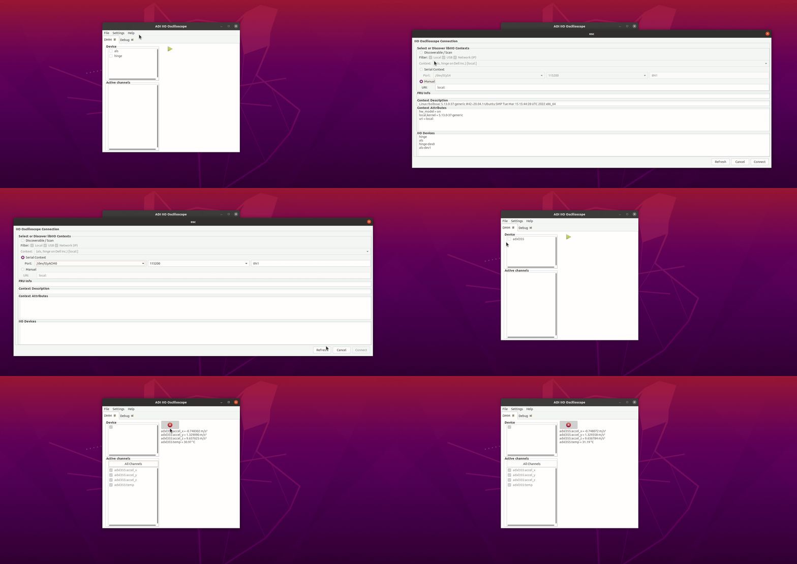
Bellow you can see the Connection window for IIO Oscilloscope. The handshake is performed and the device is detected over UART. After pressing the Connect button we can see the device in the list, together with its channels and we can see the measured data.

Below you can see the Simple View which contains the read data from the accelerometer. Observe how the measurements change.
The accelerometer is positioned such that the gravitational force is first perpendicular on its XY plane. In this case the measured acceleration on Z axis is ~g and the measured acceleration on X and Y axis is ~ 0.
The accelerometer is then positioned such that the gravitational force is perpendicular on its XZ plane. In this case the measured acceleration on Y axis is ~g, on X and Z axis is ~ 0).
Finally, the accelerometer is positioned such that the gravitation force is perpendicular on its YZ plane. In this case the measured acceleration on on X axis is ~g and the measured acceleration on Y and Z axis is ~0.

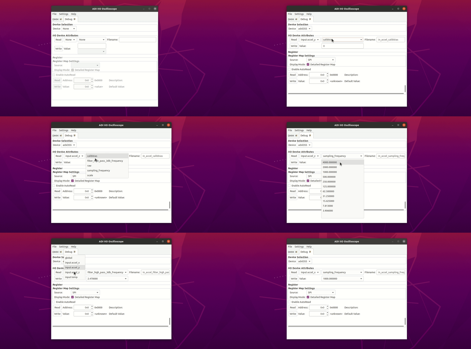
Below you can see the Debug View which contains the list of attributes for each channel of the selected device. Some attributes, like the calibbias, sampling frequency and the high pass filter corner frequency can be changed by the user, while the other attributes can be just read. You may also observe that some attributes of the acceleration channels are shared in value: sampling frequency, high pass filter corner frequency and scale while calibbias and raw attributes may have different value for each acceleration channel.

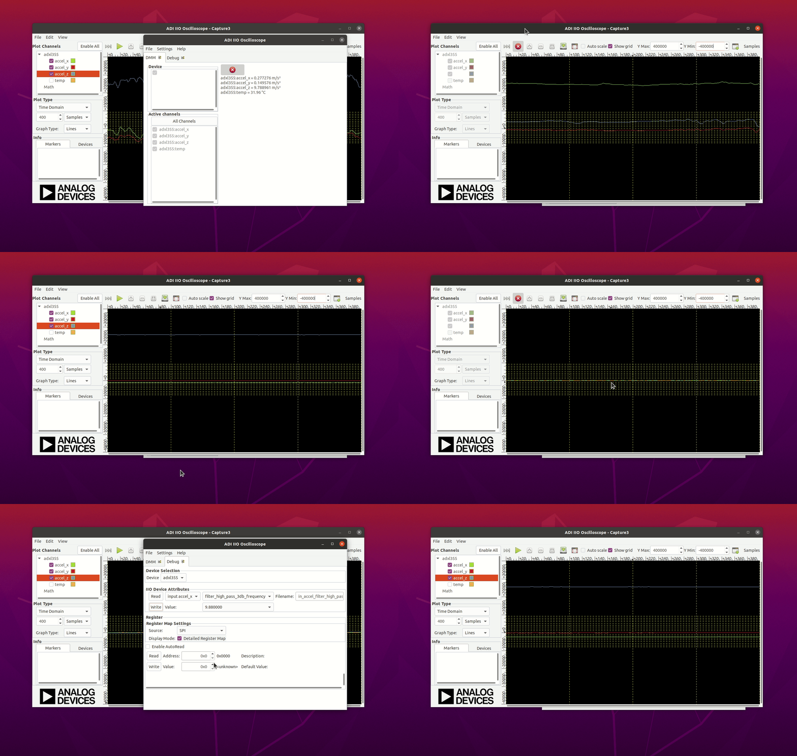
Below you can see the Plot View for the acceleration data. The Plot view shows the raw vales measured by the accelerometer. In this case the accelerometer is moved such that the gravitational force is perpendicular on XY, XZ and YZ planes. You may observe the spikes in the data due to sudden change of the accelerometer. By by applying the high pass filter, the acceleration data will be close to zero when the device is sitting still and will change when the device is moved.
 .
.