


This version (21 Feb 2024 20:40) was approved by Mark Thoren.The Previously approved version (26 Mar 2023 16:49) is available.
Table of Contents
Converter Connectivity Tutorial
Introduction
You don't have to be a software engineer in order to leverage device drivers and example code as you are evaluating and prototyping with Analog Devices' data converters and converter-like products. Selection of an ADC, DAC, or sensor often starts by finding something that meets performance requirements (obviously). This may be followed with some experimentation with the device's evaluation board and accompanying software, but at some point you need to “take the next step”. This “next step” could be any one of a wide array of things - wiring the eval board to a prototype of a larger system, deeper characterization using your own benchtop test equipment, or any one of a plethora of random requirements. This tutorial will arm you with a number of tools to this end.
Update:
The first version of this tutorial was published in early 2020, after test driving the setup with a few select field engineers. A lot has happened since then:
- ADI Kuiper Linux has matured considerably, with broad support for ADI devices and popular processor and FPGA development platforms.
- The very popular ADXL355 Pmod would have been used initially, but the Linux driver had not been upstreamed yet. It has since been released, and is being added as an option for this tutorial. (The original ADXL345 / Digilent Pmod-ACL is still included.)
- LibIIO now supports HWMON devices (if these terms aren't familiar, you'll learn about them soon), enabling the use of the absolute best device to start learning about embedded Linux systems: the LM75 temperature sensor. It is an industry standard with several manufacturers, including the Maxim LM75 and ADI's variant, ADT75
So while it's genereally not a good idea to have too many options in a basic tutorial, we felt that having a couple was appropriate here, incuding one that is very low cost (the LM75).
Analog Devices provides an assortment of evaluation boards and reference designs for converters of various channel counts, bandwidths, and other functionality, whose drivers fit into the Industrial Input Output (IIO) framework. This framework facilitates robust data transfer to or from the converter into “userspace”, where the user program could be a MATLAB script for device characterization, a Python script that talks to benchtop signal generators and spectrum analyzers via GPIB in addition to the ADI part under test, or a C program embedded in the end product. Most of these involve fairly costly reference design hardware installed on even more costly FPGA platform boards, which, to extract maximum performance, require test equipment exceeding the cost of a luxury car. So the question arises - what is the simplest, lowest cost system that captures the important aspects of these larger systems? $50 total for a Raspberry Pi, SD card, and an LM75 temperature sensor (or ADXL355 or ADXL345 board) sounds like a pretty reasonable deal. The only test equipment required is:
- You (your finger to warm up the LM75, or shake the ADXL3x5)
- The Earth (to provide a precise, low-noise, -9.8m/s2 acceleration)
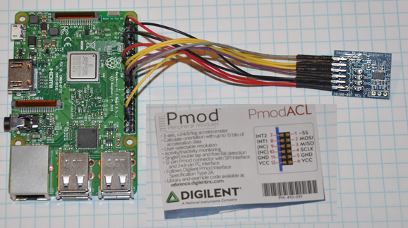
Figure 1. Ultra-simple IIO-based system
A Note on Security: The Raspberry Pi is a fantastic tool, but it can represent a network security gap if used improperly. Our Raspberry Pi will start out configured in a fairly open state - a simple root password, SSH login enabled. This isn't an issue if the Raspberry Pi does not have internet access or is behind a firewall, but if you are going to connect to your network, it's a good idea to change the password to something secure. Refer to this article on Raspberry Pi Security:
Securing your Raspberry Pi
A Note on the Tutorial: This tutorial is hands-on, and attempts to be clear and consistent. But there are often several “right” ways of doing a step - choice of editor to modify files on an SD card, using a Windows, Mac, or Linux machine, etc. When in doubt: Double-check your wiring, and just try stuff. Worst case, you'll need to re-burn your SD card to get back to the starting point.
Representative systems
We are intentionally starting with an extremely simple example. But once you understand how to communicate with an LM74, ADXL345, or ADXL355, you're well over the intitial learning curve to understanding much more complicated systems. The ADALM-Pluto is a great example - it contains an AD9363 RF Agile Transcieiver, Zynq SoC FPGA, Memory, USB interface, and much more. Even the simplified block diagram is pretty daunting:

Figure 2. Pluto Simplified Block Diagram
If the Pluto wasn't scary enough, the Phased Array (Phaser) Development Platform might be a step in that direction. It incorporates two ADAR1000 beamformers, an ADF4159 Fast Waveform Generating, 13 GHz, Fractional-N Frequency Synthesizer and uses the Pluto as its IF digitizer. It's also got a AD7291 8-Channel, I2C, 12-Bit SAR ADC with Temperature Sensor for basic monitoring; a simple device by comparison, but it's got its own device driver, and is adjacent the more complex devices both physically and in software.

Figure 3. Phaser System Overview
But - all of the phaser's devices work together, and by the time you finish this tutorial you'll be able to chip away at understanding how the individual devices work, and eventually, how they whole system works.
Connecting the Hardware
Before we dig too deep into software stuff, let's prepare the hardware. There are lots of ways to connect boards together, custom adapters, Raspberry Pi prototyping hats, etc. The PMD-RPI-INTZ is an interposer that simplifies connecting I2C and SPI Pmod boards, QuikEval compatible eval boards, and Power System Managemement (PSM) eval boards to a Raspberry Pi. Figure 4 shows the ADXL345 Pmod (available directly from Digilent and from various distributors) mounted to the PMD-RPI-INTZ board. Note that the Pmod must be installed on P1, which uses SPI CS0 and has the interrupt pin connected to GPIO 19.
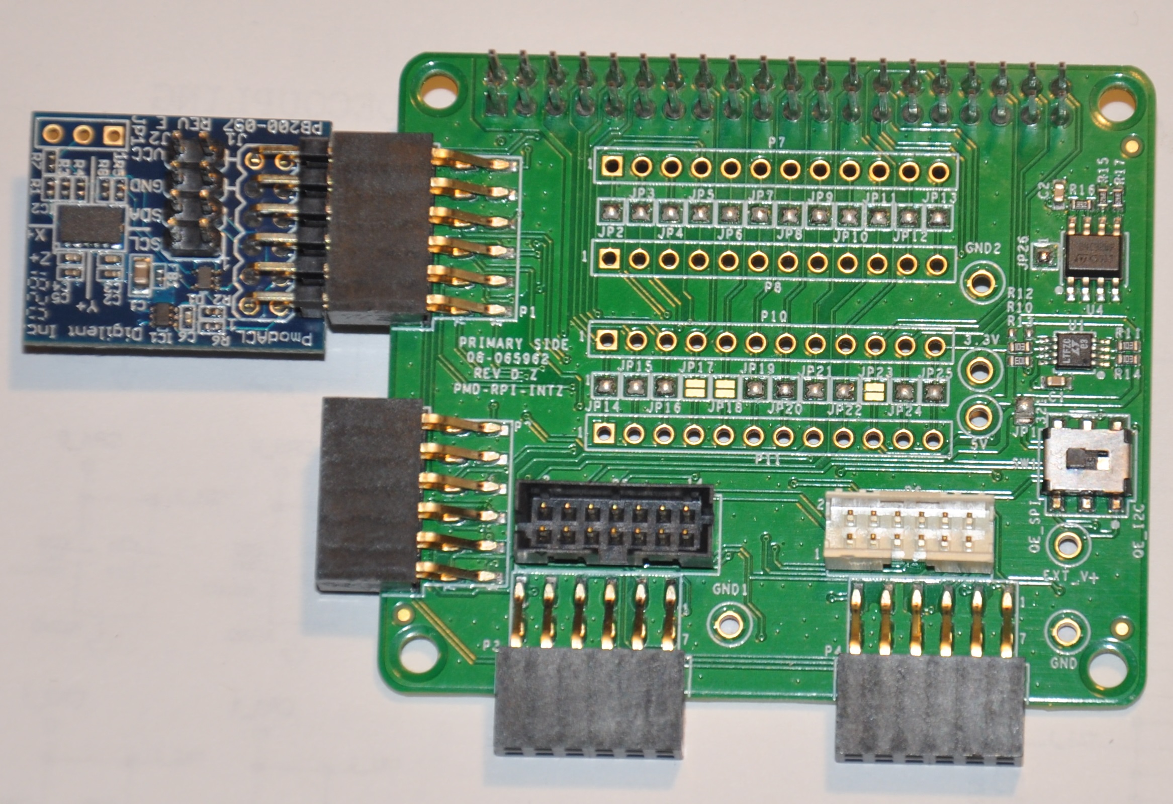
Figure 4. ADXL345 Pmod Mounted to PMD-RPI-INTZ Interposer
Another option that generally applies to eval boards with test points on the digital signals is to use discrete jumper wires. Five inch jumpers from Schmartboard: Schmartboard Jumpers are very convenient.
If you are using Jumpers, use Figure 1 as a visual aid and make the connections shown in Figure 5. The accelerometer board is a Digilent model Pmod:ACL, It is essentially a breakout board for the ADXL345.
In theory, any Raspberry Pi should work, although it is probably best to use a modern model with a 40-pin expansion header. (The model shown in Figure 1 is a model 3B, version 1.2.)
Note that there are TWO SPI ports - SPI0 and SPI1. We will be using SPI0 (Pins 8, 19, 21, 23)

Figure 5. RPi-Pmod connections
To Do:
Add detailed pictures of ADXL355 Pmod and options for LM75 and ADT75.
In the meantime - it's straightforward:
- The ADXL355 Pmod plugs into the same P1 location on the PMD-RPI-INTZ
- The Digilent Pmod TMP3 uses the compatible Microchip TCN75A temperature sensor. It's not the most convenient; it's not truly Pmod compatible because the header is mounted vertically, the easiest way to connect it to the Pi is with Schmartboard jumpers.
- The Analog Devices LM75 and ADT75 don't have convenient eval boards so the best option is to solder them to breakout boards
- There are several “maker style” LM75 breakout boards offered by your favorite online vendors that should work fine.
Burning SD cards
In order to boot the Raspberry Pi, you will need to obtain an SD card “image”, and write (or “burn”) it to a card. We'll talk about where to get the correct image shortly. This is a fairly common step in bringing up embedded computers - Raspberry Pi, BeagleBone, Zedboard, Arrow SoCkit, or any machine that boots from an SD card. There are lots of ways to burn images, but the most straightforward way is to use the standard Raspberry Pi Imager, available here:
Raspberry Pi OS (including Raspbery Pi Imager
There are instructions for Windows, Mac, and Linux. The imager also works on machines that encrypt data being written to external drives since it's writing “raw” data. HOWEVER - beware encryption software when editing configuration files! (More on that later…)

Figure 6. Raspberry Pi Imager Screenshot
A new SD card is usually preformatted as a single EXFAT partition, usable by all operating system. But after burning an image to the card, it will show up as several partitions, not all of which are visible to all operating systems. So if you burn a card in Windows, and a popup appears saying “This drive needs to be formatted, would you like to format now?”, the answer is NO! Figure 7 shows the SD card partitions before and after burning the image. Attempting to read the partition map in Windows (under Administrative Tools, Disk Management) will show the ext4 partition as “unknown”

Figure 7. SD card partitions before and after “burning”
Helpful Hint: It may happen that an SD card becomes corrupted somehow. This can sometimes be fixed in Windows by opening storage manager in Administrative tools, then removing all partitions, and reformatting as EXFAT (a similar procedure can be followed using fdisk in Linux.) But computers are smart - sometimes too smart - and there are cases where these tools fail to repartition a drive. However - digital cameras are not as smart, and using a digital camera's (such as a Nikon D90) SD card formatting feature will often resurrect a “bricked” card.
ADI Kuiper Linux
What is “ADI Kuiper Linux”? Here's a little glossary:
- Debian = A Popular Linux Distribution
- Raspberry Pi OS = Debian customized for Raspberry Pi
- ADI Kuiper Linux = ADI's Raspberry Pi OS variant with extra goodies:
- All drivers for ADI, LTC parts that make sense enabled
- Boot files for FPGA-based reference designs and evaluation boards targetting a number of popular FPGA platforms, including:
- Data acquisition and transciever boards (FMCOMMSx, FMCDAQx, etc.)
- ZedBoard, Digilent Cora Z7, ZCU102, Intel DE10-Nano, Arria 10 SoC dev kit
- LibIIO, IIO Oscilloscope, other ADI programs and utilities.
- iiod runs at startup
- GNURadio
More information on Raspberry Pi OS can be found at Raspberry Pi OS. Raspberry Pi OS includes lots of fun stuff - Minecraft, an office suite, web browser, sound processing labs, other games, etc. We won't cover any of that, but do explore on your own!
(More information on the Kuiper Belt can be found at Kuiper_belt)
The SD card image is available here:
Analog Devices Kuiper Linux
Download the compressed zip file, and extract the .img file. (tar.gz files can be extrtracted using 7zip in Windows.) Follow the procedure for burning SD cards above, using a 16GB (or larger), high-quality, Class 10 or faster SD card.
At this point, you should be able to:
- insert the card into the Raspberry Pi
- Connect an HDMI monitor
- Connect a USB keyboard and mouse
- Supply power via a micro-USB cable and old phone charger.
Note: It is possible to use the Raspberry Pi without a local keyboard, mouse, monitor - see the “Going Headless” section below.
If all goes well, you should see a desktop. From the start menu, click Other → IIO Oscilloscope (or open a terminal and run IIO Oscilloscope):
analog@analog:~$ sudo osc
(Enter the root password, “analog” by default unless you followed the advice above to change it.) You should then see IIO oscilloscope running as shown in Figure 8! Also note that IIO Oscilloscope will run without root privileges, but all devices will be read-only. For example, you won't be able to change the ADXL3x5's sampling frequency, or LM75's over/under temperature thresholds.

Figure 8. Raspberry Pi w/ ADI Kuiper Linux desktop
But… if you look at the IIO oscilloscope panels, where's the ADXL3x5 or LM75? Well, the Linux kernel does a bunch of stuff during boot, controlled by various configuration files (remember autoexec.bat and config.sys on old DOS systems?, Yup, the authore has suppressed that memory, too.) One of them, /boot/config.txt, is how you tell Linux about what hardware is connected, and the default is NOT the ADXL345… so let's fix that.
Device Tree Overlays
When we first powered up the Raspberry Pi and ran IIO Oscilloscope it didn't find anything. While we do have our ADXL3x5/LM75 physically connected to the board, Linux doesn't know about it yet because UNlike USB, PCI, SCSI, Firewire, HDMI, etc, SPI and I2C devices do not support enumeration. How do we tell the Linux kernel what we've connected to the expansion header? The answer is the “Device Tree Overlay”.
While you won't have to do anything more than editing a couple of files in this tutorial, it helps to understand a bit about what is going on under the surface. A “Device Tree” contains information about a system's hardware - what peripherals exist (like displays, memory, USB, Ethernet controllers, GPIO pins, etc.) A “Device Tree Overlay” contains information about additional connected hardware, like our ADXL3x5/LM75. Figure 9 shows a screenshot of the ADXL345's overlay source. It shows that the ADXL345 is connected to the SPI port, using the first CS signal (CS0), the maximum SPI clock frequency is 1MHz, and the interrupt signal is connected to Pin 19 (as shown in the connection diagram above.)

Figure 9. Partial ADXL345 overlay source (dts)
The device tree source is then compiled into a “flattened” device tree that the Linux kernel reads directly. While this process is fairly straightforward, it's beyond the scope of this tutorial. Furthermore, the device tree overlay for this tutorial is already included on the SD card, along with several other overlays for other hardware configurations. (Note that the device tree overlay is specific to a particular device AND how it is connected to the Raspberry Pi. Any changes to the connections - SPI CS line, interrrupt line, etc. will require a corresponding modification to the overlay.)
For reference, here are the overlay source files for the three devices in this tutorial. These are in the Linux rpi-5.15.y branch, used for Kuiper Linux 2022_r2 release:
For more gory details on device trees, a great resource is Device Tree for Dummies by Thomas Petazzoni.
So keeping with the spirit of doing while we're learning, let's configure the overlay for this experiment. The device tree overlay is specified in the config.txt file, which lives in the BOOT partition on the SD card. There are several ways to edit this file - Since the BOOT partition is a FAT filesystem, you can use any text editor on any operating system; Notepad on Windows, Kedit on Linux, etc. Or… if your Raspberry Pi is booted up, you can edit directly on the Pi! Just open a command prompt, and type:
analog@analog:~$ sudo mousepad /boot/config.txt
which will bring up the file in the Mousepad editor. Scroll down until you find the line that begins with “dtoverlay”, and, whatever it happens to be, change it to:
dtoverlay=rpi-adxl345
# dtoverlay=rpi-adxl345
# dtoverlay=rpi-lm75,addr=0x48
dtparam=act_led_trigger=heartbeat
dtoverlay=gpio-shutdown,gpio_pin=21,active_low=1,gpiopull=up

Figure 10. Editing config.txt directly on Raspberry Pi
Notice the two commented lines beginning with #. As you might expect, you should UN-comment the appropriate line for the device you have connected.
Notice that there are a couple of additional lines - there are lots of useful optional parameters that can be set in the config.txt file, here we're setting the onboard LED to the “heartbeat” function, this makes it easy to see if the board is running or shut down, even if you don't have a display connected. The other line turns GPIO21 into a hardware shutdown function, also very useful if you are operating the board without a display.
If you want to make it easy to revert back to some other overlay, comment out the original line with a pound sign / hashtag:
#dtoverlay=rpi-something-other-than-adxl345
dtoverlay=rpi-adxl345
One last thing worth noting - the default video resolution is 1920×1080. If this causes problems with your monitor, hanging hdmi_group, mode to 2, 58:
hdmi_group=2
hdmi_mode=58
will set the screen resolution to 1680×1050. Information on other video modes is available here:
However you edit the file, save, close, cross your fingers, and… reboot! You can do this from the start menu, or from a terminal type:
sudo reboot
To shut down at the end of the day, type:
sudo shutdown -h now
Hello, ADXL345, ADXL355, or LM75!
If all went well, Linux should have booted, found the ADXL3x5 or LM75, and loaded its driver. Run IIO Oscilloscope again. locate the DMM screen, check the ADXL345, select all channels, and click the triangular “play” button. You should see acceleration values displayed as shown in Figure 11.

Figure 11. IIO Oscilloscope showing ADXL345 channels
IIO Oscilloscope is a great tool for establishing signs of life, but really isn't intended for much more, so let's start digging deeper into how to communicate with the ADXL345 programmatically. Close out of IIO Oscilloscope, open a terminal and enter:
analog@analog:~$ iio_info
You should see the screen filled with information about the ADXL345 - sample rates, “raw” values, scale values, etc. This means that you're ready to start writing programs to do useful stuff with the ADXL345… on the Raspberry Pi itself. But before we go there, let's introduce one more extraordinarily powerful feature of the IIO framework - the ability to communicate remotely over a network connection. This ability is made up of two components: an IIOD server running on the Raspberry Pi, and LibIIO running on the remote machine. LibIIO is cross-platform, so client applications can be written on Windows / Mac / Linux.
Let's take a peek at the IIOD server. In the Raspberry Pi terminal, enter:
analog@analog:~$ ps aux | grep iiod
Which means “list all processes from all users, but only display ones that include the text “iiod””. You should see a process running as shown in Figure 12 below. (Note that this is the login screen for an ADALM2000 - it's all the same.)
And the red line relates this process back to the handy little diagram from What is Libiio? (We will be recycling that diagram - a lot.)
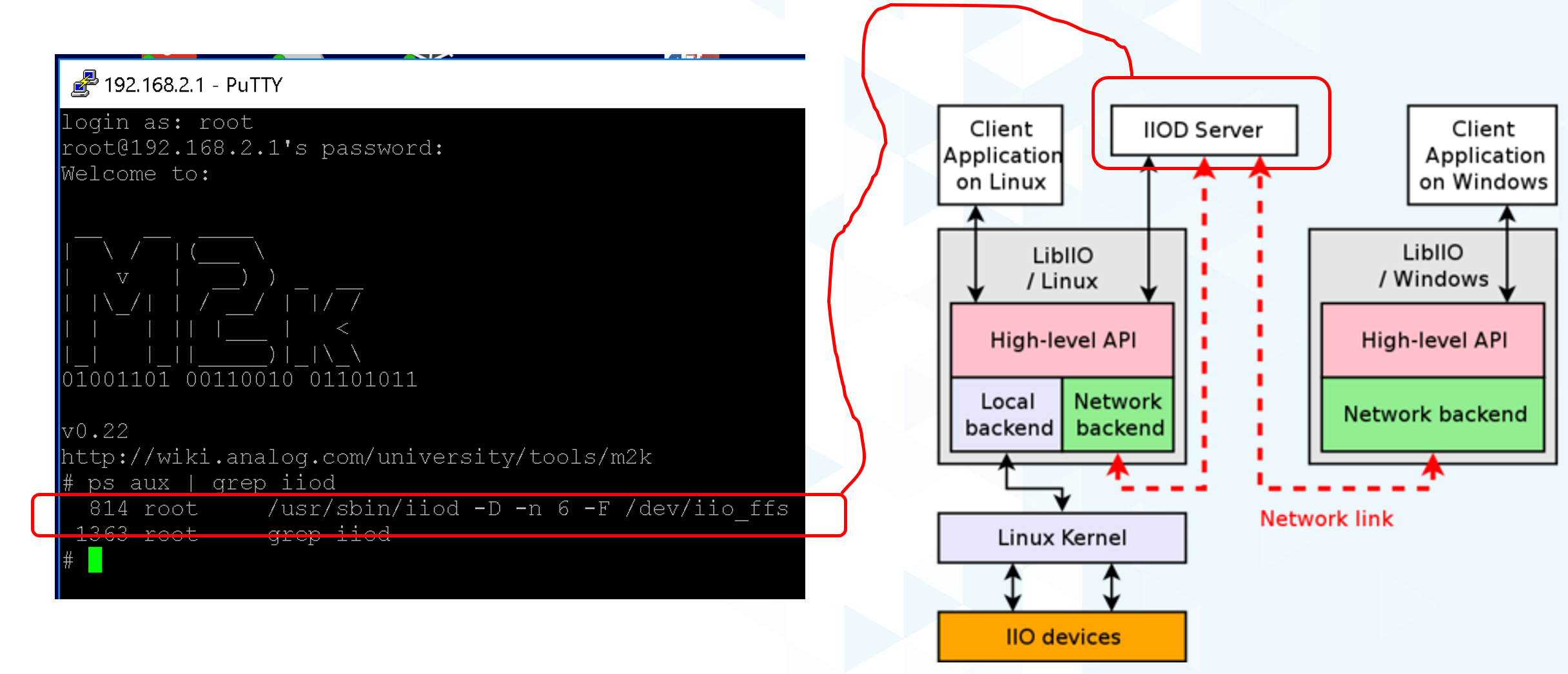
Figure 12. IIOD process
The other piece is libiio on the remote host. LibIIO can be obtained from:
Download and install the appropriate latest version for your remote host (For example, libiio-0.24.gc4498c2-Windows-setup.exe for Windows) Once this is done, open a command prompt, and enter:
iio_info -u ip:analog.local
(Where the IP address may be different, depending on how you've connected.) If all goes well, you should see lots of information associated with the ADXL345… that is connected to your Raspberry Pi… but from your Windows / Linux / Mac machine! (How cool is that?)
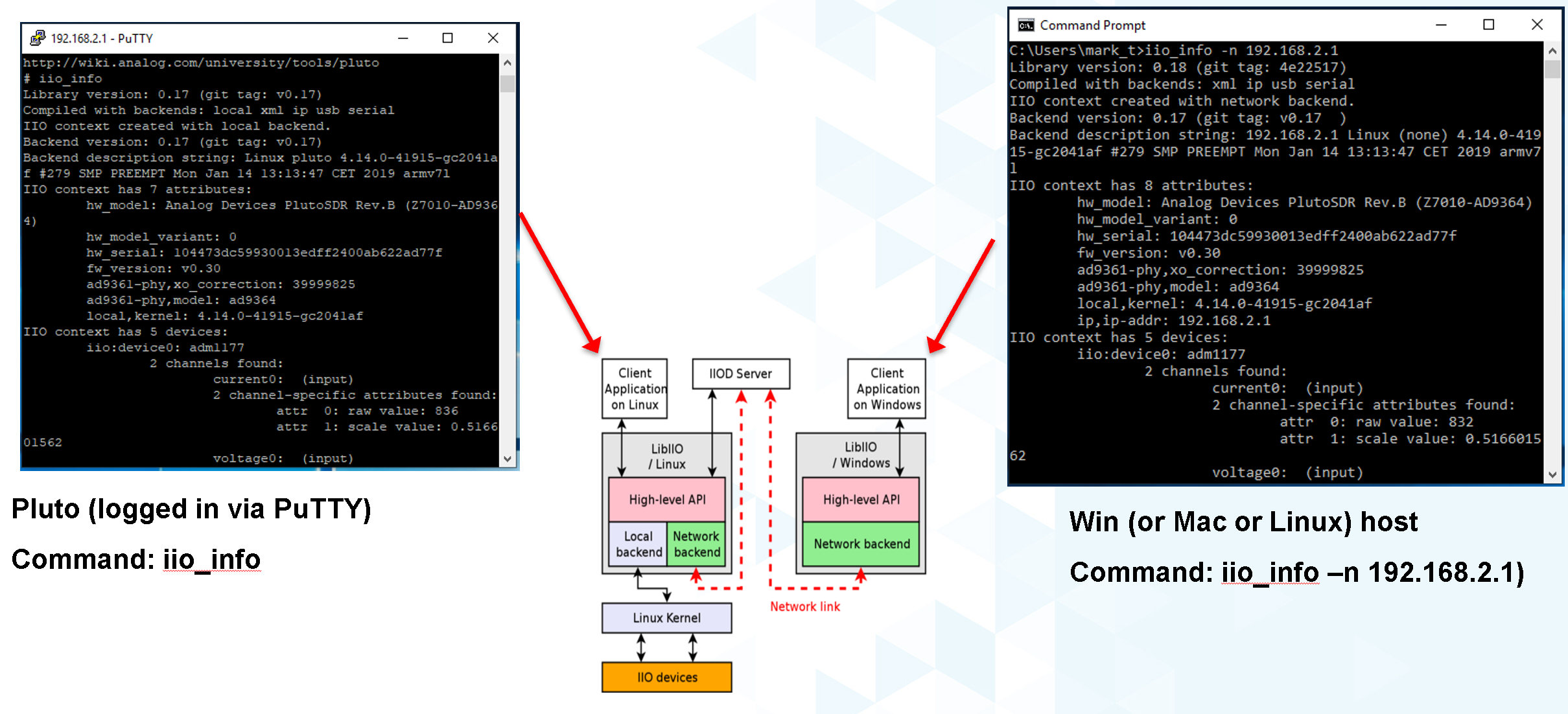
Figure 13. iio_info run locally and remotely
NOW you've got all the pieces for some fun hacking - you can write software that runs directly on the Raspberry Pi and talks to the ADXL345 (which… is conceptually similar to writing software that runs on a Xilinx SoC board and grabs data from an attached high-speed ADC) AND, you can write software on a remote host - useful if you want a larger application that is more appropriate to run on the host, or if you want to grab large amounts of data for analysis.
LibIIO is written natively in C, but there are bindings for MATLAB, C#, and Python. Let's use Python…
Python
Any language that can call a shared library can communicate with libiio. But Python is attractive for getting started for several reasons:
It's FREE It's tremendously popular It's got tons of number crunching libraries It's got tons of libraries for communicating with hardware (It's also really really fun!) And - it's easy to learn. If you've never touched Python before, there are lots of free resources, including this 4-hour course on YouTube from freeCodeCamp.org:
And this very nice interactive tutorial:
Learn Python
in which code snippets run in the browser (no need to intall Python.)
If you prefer paper, Python for Kids by Jason R. Briggs is a well written books for kids of all ages. (And Learn to Program with Minecraft: Transform Your World with the Power of Python by Craig Richardson is a pretty nice introduction to the idea of communicating over a network connection; the Minecraft world is a process that communicates over network ports.)
There are several choices of Python installations, and which one to use is largely a matter of preference. You can install from scratch from Python.org, or a more full featured distribution such as Anaconda, PyCharm, or VS Code. And Python is pre-installed on ADI Kuiper Linux, as is the Thonny IDE. Thonny is basic as far as IDEs go, but it provides breakpoints, variable watches, and is perfectly adequate for simple to intermediate development.
On Python Versions - We're using Python 3 (3.9.2 in Kuiper 2022_r2 to be specific.) So if you're installing on your remote host, make sure to get a recent version of Python 3.
Previous Kuiper Linux releases had multiple Python versions installed, defaulting to Python 2.x. The current Kuiper Linux defaults to Python 3 so this is no longer an issue, but for historical curiosity the procedure for setting the default to Python 3 is to run the following commands:
analog@analog:~$ sudo update-alternatives --install /usr/bin/python python /usr/bin/python2.7 1
analog@analog:~$ sudo update-alternatives --install /usr/bin/python python /usr/bin/python3.7 2
(This only needs to be done once.)
PyADI-IIO
PyADI-IIO (pronounced “Py-odi”1) is like peyote, but with a Py) is a python abstraction module for ADI hardware with IIO drivers to make them easier to use. Pyadi-iio can be installed through pip, and is pre-installed on ADI Kuiper Linux, but if you're reading this you'll probably want to be hacking around a bit so go to PyADI-IIO Github Repo and follow the “installing from source” instructions. And note that this can be done on your remote Windows / Mac / Linux host AND… on the Raspberry Pi itself! Git is already installed on ADI Kuiper Linux, but may need to be installed on a Windows host. (You can also download the repository as a zip, but cloning will make it easier to update.) Let's install pyadi-iio.
analog@analog:~ $ git clone https://github.com/analogdevicesinc/pyadi-iio.git
analog@analog:~ $ cd pyadi-iio
analog@analog:~/pyadi-iio $ sudo pip install .
Note: This requires that your Raspberry Pi be able to access the internet. If you've followed the “headless” instructions below, this may not be the case. However - if you have access to a wireless network and your Raspberry Pi has an Ethernet adapter, you can connect in this way. Just click the WiFi icon and log on as you would on any other machine, supplying a password if necessary

Figure 14. WiFi logon
Now it's (almost) trivial to grab data from the ADXL345 used in this tutorial, as well as more complicated hardware. With pyadi-iio installed, you should be able to run the ADXL345 example.
To Do:
Update ADXL345 pyadi-iio example.
As of Feb. 2024, the ADXL345 example has a hardcoded ip address. Most newer examples allow the context to be passed via command line argument, but in the meantime change line 10 from:
myacc = adi.adxl345(uri="ip:192.168.1.232")
to:
myacc = adi.adxl345(uri="ip:localhost")
Enter the following commands, making sure you're in the pyadi-iio root directory:
analog@analog:~/pyadi-iio $ cd examples
analog@analog:~/pyadi-iio/examples $ python adxl345_example.py
The example program takes a few acceleration readings, shows how to set the sample rate, and shows how to convert values to SI units.
If you're running the example on the remote host, you should be able to talk to the Pi by using the context “ip:analog.local”, the address noted for the “headless” configuration below. If your Raspberry Pi's address is different (supplied by DHCP, for example), change it accordingly. The example will also run locally, with the same IP address! But as soon as the IP address changes, the example won't work any more. Since we're running locally, you can set the IP address to the local loopback address:
myacc = adi.adxl345(uri="ip:localhost")
But since we're running locally, why bother talking through IIOD? Setting the context to local takes care of that:
myacc = adi.adxl345(uri="local:")
But there's one subtlety… run Python as root ( sudo python adxl345_example.py ). The reason is that IIOD runs with root privileges and can read / write to devices. The example script will be able to read just fine, but writing even something as mundane as the sample rate requires root privileges.
The example script should run just fine on the Raspberry Pi itself, and on the remote host. Try writing a program to read out a hundred samples from each channel (X,Y,Z) and store to a file, or if you're really adventurous, display the 3-axis acceleration as an arrow in a graphical screen.
The ADXL355 and LM75 examples allow the IIO context to be passed as a command line argument. From the command line, run the following for the ADXL355:
analog@analog:~/pyadi-iio/examples $ python adxl355_example.py ip:localhost
And this for the LM75:
analog@analog:~/pyadi-iio/examples $ python lm75_example.py ip:localhost
Tools for your Toolbox: SSH, SCP, VNC
Putty and TeraTerm are popular (and free) SSH clients that let you log into a console on your Raspberry Pi (or other remote client). They are available at PuTTY Homepage and TeraTerm Homepage , respectively. Try both, which one is better is largely a matter of preference.
On Mac and Linux machines, you can simply log in via ssh from the command line.
WinSCP is a handy tool that lets you copy files between a Windows machine and your Raspberry Pi, for example, let's say you collect some data on your Pi using a Python script, and want to get it over to your Windows machine. It is available from WinSCP Homepage.
As with SSH, Mac and Linux machines include SCP already.
VNC is a remote desktop application, and Kuiper Linux runs a VNC server by default. There are several clients available; RealVNC works well and is available at RealVNC Viewer A screenshot of VNC logged into the Raspberry Pi is shown in Figure 15.
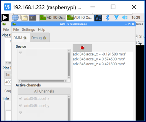
Figure 15. VNC desktop
Going "Headless"
(Ignore if you're using a monitor / keyboard / mouse)
If it happens that you don't have a spare monitor / keyboard / mouse, or it's just inconvenient, you can operate the Raspberry Pi with only a network connection. By default, the ADI Kuiper Linux network hostname is analog, and the machine can be accessed as analog.local.
The Raspberry Pi can also be accessed directly by its IP address. If your network has a DHCP server, and you can find the IP address that it assigned to the Raspberry Pi, you're all set. But a very robust way is to set the Raspberry Pi's address manually, and do the same to one network adapter on the host. To set the Raspberry Pi's address, open the boot partition on a host machine (once again… BEWARE ENCRYPTION!), and note that this host machine could be the Raspberry Pi itself, with a montior / keyboard / mouse attached. Open the file “cmdline.txt” and add the following to the end:
ip=192.168.1.232::192.168.1.1:255.255.255.0:rpi:eth0:off
where, the 192.168.1.232 is somewhat arbitrary - just make sure that the first 3 octets (192.168.1) are DIFFERENT from those of any other network adapters on your host machine. The next step is to configure your host's network adapter. Open your computer's “Network Connections” control panel note that your host could have lots of adapters. Sometimes it's obvious - if you're using a cable connection, it's obviously NOT your wifi adapter. If you're using a USB-Ethernet adapter (a super convenient option sometimes), plugging and unplugging the adapter, and seeing which disappears. Open the adapter's configuration (right-click, “Properties”) and configure the IPV4 properties as shown in Figure 16 below. Make sure the last octet in the IP address is DIFFERENT from that set on the Raspberry Pi.
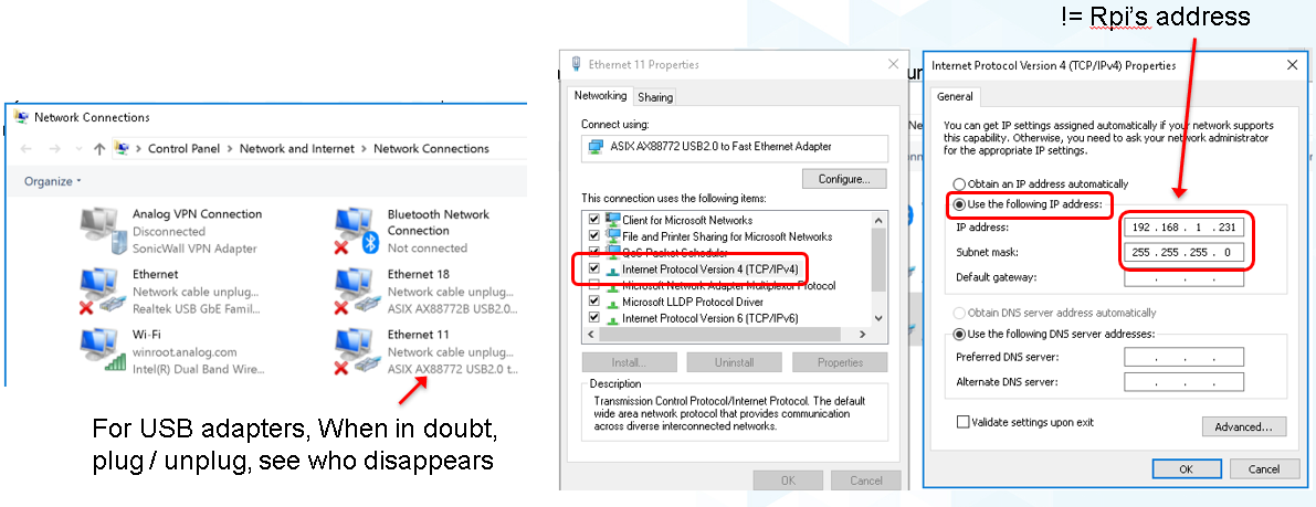
Figure 16. Setting Up Static IP on Windows Host
Finally… open a command prompt, and ping your Raspberry Pi as shown in Figure 17:

Figure 17. Pinging the Headless Pi
If you get a reply, you're all set! You can now log into the Raspberry Pi using PuTTY, VNC, and talk to attached IIO devices via IIO oscilloscope or libiio on the remote host.
Leveraged Learning: This process (and any frustrations accompanied on the way) is the same for using any network connected embedded computer, test equipment, etc.
Conclusion
You're now armed to start building interesting application circuits with the ADXL345, starting with a solid software foundation. Applications can either be connected to a host computer, or can run remotely on the Raspberry Pi itself. Hopefully you're left with one of two feelings:
- Device drivers look really complicated, thank goodness I can dive in as a user and do something useful without having to fully understand the details. (If this is the case, see if the devices you're using in your present work are supported in ADI Kuiper Linux, and try to get them up and running.)
- This is really interesting! I want to know more! (If this is the case, great! A good starting point would be Building for Raspberry PI)
1)
pei·ow·tee : 'p' in pie; 'a' in about; 'y' yes; 'o' in code; 't' in tie; 'y' in happy
university/labs/software/iio_intro_toolbox.txt · Last modified: 21 Feb 2024 20:40 by Mark Thoren