


This version (29 Jun 2017 15:26) was approved by Venkatesan Krishnamoorthy.
Table of Contents
Real Time Variant
Click here to return to the Master Control Port section.
The Variant Editor is a SigmaStudio tool that helps the users utilize different variations(variants) of their original audio program flow already programmed into an external memory.
A Variant is a set of parameters from the current schematic. Real Time variant module allows users to create multiple variants. Parameters selection for a variant can be done through drag and drop from capture window to the variant configuration form. The parameter addresses and values in the variant are stored in the EEPROM after the self boot image. Address for each of the variant in EEPROM can be either updated by the users or can be generated automatically.
Module allows users to select a variant dynamically through external input pin. It takes an input index in 32.0 format to select the current variant from EEPROM. The module will read the variant (parameter set) corresponding to the input index from the EEPROM and replaces the actual parameters in the run-time whenever input index is changed.

Input Pins
| Name | Format [int/dec] - [control/audio] | Function Description |
|---|---|---|
| Pin 0: Variant Index | int- control | Acts as the selection index for variant data copy. |
Output Pins
The algorithm does not contain any output pins.
Grow Algorithm
The module currently does not support grow/add functionality and only one instance is supported.
Configurations
Follow the steps shown below to configure real time variant module.
- Create a SigmaStudio audio flow that compiles without any errors.
- Drag and drop 'Real Time Variant' module and connect a DC source to it. Then change the fixed point format of DC source to 32.0

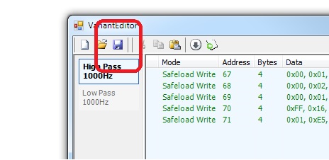
- Click on the image
 to open variant editor window.
 - Clear capture window in the SigmaStudio. Then modify any module's parameter to the desired value. The parameter changes will be displayed in capture window.

- Select the desired parameter writes (including Safeload writes) from the Capture window. Drag and drop these parameters into the Variant Editor.

- To add another variant, simply right click on the left side of the window, under the previous mode. A menu item window box will appear with many options. Select 'Add Mode' option.

- In order to give relevance to the variant design, it is good practice to give variants a descriptive name. To do so, just double click on the variant name, the name will be highlighted and ready to be edited. An alternative way to change the name is by right clicking on it and select “Rename…”

- Drag and drop parameters from capture window to other variant modes in the similar way.
- Once the all the variants are configured. Press 'Save' button in the Variant Editor. This will save the variant information in XML format. (File is stored in the location where the schematic is present)
- Press 'Update' button in the Variant Editor tab. This will update the variant table with the EEPROM address and the size of the variant. Variant editor also displays the current program length and how much memory program will occupy in the Self-Boot EEPROM.

- User can edit the auto calculated EEPROM variant addresses by un-checking the 'Auto Calculate Variant Addresses' option.
- Update EEPROM properties and SPI/I2C properties in the 'EEPROM Editor' tab. I2C address for the EEPROM is assumed as 0xA0 (8-bit address) and slave select for the SPI is 0.

- User can test Variant information before programming the external memory. Find the button with a green arrow over a white window icon (last button). When hovering over this button it should read “Launch Sequencer Window”. Click on it and the stand-alone sequencer window will pop up displaying four buttons in a grid. By clicking to any of these buttons, the current program that runs on the DSP should start changing accordingly. In a similar fashion, by selecting the variant name and clicking the grey arrow will download that variant parameters to the DSP.

- Please note that whenever there is a change in the schematic, press Update button to update the parameter addresses in the variant window.
- Once all the variants are working as expected, it is time to program the external memory. To begin this process, go to 'Hardware Configuration' tab. Then right click on IC then select 'Write Last Compilation through DSP' option.

- The “EEPROM Properties” window will appear. Fill this window with the proper memory manufacturer specifications. On this example we're using a 1 Mbit SPI Bus Serial EEPROM. This information will be used to program the whole program and data memory along with variant information to the EEPROM, using these parameters to load the program at boot time into the DSP while self-boots.

- After the EEPROM programming is completed. Reset the board and change the Variant selection index(DC module) to select different variants. DC value 0 will select first variant, DC value 1 will select the second variant and so on.
Using GPIO to select Variants
The GPIOs can be used to select the variants instead of a DC module.
- Connect GPIOs to Binary to Decimal module.
- The output of 'Binary to Decimal' module can be connected to 'Real Time Variant Module' as shown below.

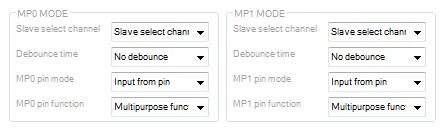
- Configure the used GPIO pins in register window as input multipurpose pin.
 The table below captures the GPIO value to the variant selection.
| GPIO_0 | GPIO_1 | BinToDec module's output (32.0) | Variant Mode Selected |
|---|---|---|---|
| 0 | 0 | 0 | Variant Mode 0 |
| 1 | 0 | 1 | Variant Mode 1 |
| 0 | 1 | 2 | Variant Mode 2 |
| 1 | 0 | 3 | Variant Mode 3 |
Supported ICs
- ADAU145x
resources/tools-software/sigmastudio/toolbox/mastercontrolport/realtimevariant.txt · Last modified: 09 Mar 2017 12:08 by Venkatesan Krishnamoorthy