This page gives an overview of using the 'ARM Mbed' platform supported temperature measurement firmware example with Analog Devices AD7124 Evaluation board and SDP-K1 controller board (or any other Mbed supported target board). The firmware example is console based, which provides an user-interactive menu options for user to select and configure the multiple temperature sensors at different instances, such as 2/3/4-wire RTDs, NTC Thermistors and Thermocouples.
The connection block diagram is described below:

For AD7124 evaluation board connections and jumper settings, refer the respective evaluation board manual. Arduino connector is used as default interface type for both the boards in the software.
SDP-K1 is powered through USB connection from the computer. SDP-K1 acts as a serial device when connected to PC, which creates a COM Port to connect to serial terminal (console based application) running on windows-os. The COM port assigned to a device can be seen through the device manager for windows based OS.
This section briefs on the usage of MBED firmware. This also explains the steps to compile and build the application using mbed and make based build.
Source code is hosted here:
Build Guide for Precision Converters MBED firmware (Use below link):
If you are familiar with the Mbed platform, the following is a basic list of steps required to start running the code:
Configure your serial terminal ( Tera Term) for below settings:
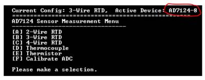
The AD7124 temperature measurement example main menu looks like below (with Tera Term):

Firmware allows user to perform the measurement for single or multiple (more than one) temperature sensors of same type. Below sensors are supported:
User must ensure all sensors are connected to AD7124 evaluation board as per configurations specific in the software and on this wiki page (see subsequent sections). If user intend to change these configurations in the software, the hardware connections must be modified as per new configurations. The details about altering the software modules for modifying the configurations are given in 'Modifying Firmware' section.
Firmware provides an option for user to perform calibrated measurement on 3-wire RTD sensors. There are two types of calibration options available in the firmware. User must modify sensor hardware connections according to configuration defined in the software. Based on selected calibration type, the sensors are first calibrated and then 3-wire RTD measurement is performed on them. For more information on the calibration scheme, refer the design note on RTD measurement.
Firmware allows user to perform ADC calibration on the current sensor configuration (demo mode) selected through console menu. ADC calibration helps to remove any offset Or gain error present on the input channels. The updated device coefficients (gain and offset) post ADC calibration are used/applied during the sensor measurement. Therefore, once calibration is complete, user must go to the previous demo mode which was selected before ADC calibration and then perform the measurement on selected sensors. The calibration coefficients (gain and offset) are applied only on the analog input channels which were enabled prior to calibration. Also after calibration if any new demo mode is selected apart from the one which was enabled during calibration, the calibration coefficients are reset and doesn't applied on input channels. In this case, user must perform the calibration again.
Internal ADC calibration is straightforward but system calibration needs user inputs (typically after applying full-scale/zero-scale) voltages on selected analog inputs.
This file can be used to:
This file defines the analog inputs, excitation sources, PGA, reference sources and power mode for all sensor demo mode configurations.
These files define the AD7124 register configurations used for various sensor demo modes.
This file defines the user configurations for the AD7124, such as SPI parameters (frequency, mode, etc) and other init parameters used by No-OS drivers to initialize AD7124 device. These are the parameters loaded into device when device is powered-up or power-cycled.
This file defines the functionality for selecting and displaying sensor configurations (hardcoded in the software), perform ADC sampling on selected sensor channels and display temperature measurement result for selected sensors.
This file defines the functions which acts as wrapper for calling 'tempsensor' library functions to calculate the temperature based on resistance or voltages. The fixed sensors such as NTC 10K, T type thermocouple, PT100/PT1000 RTD are used.
No-OS drivers provide the high level abstracted layer for digital interface of AD7124 device. The complete digital interface (to access memory map and perform data read) is done in integration with low level platform drivers.
The functionality related with No-OS drivers is covered in below 2 files: