 This version is outdated by a newer approved version.
 This version (01 Feb 2016 16:40) was approved by Brandon Bushey.The Previously approved version (26 Jan 2016 22:49) is available.
This is an old revision of the document!
The ADuCM360_demo_cn0357 is a toxic gas(CO) detector demo project for the EVAL-ADICUP360 base board with additional EVAL-CN0357-ARDZ shield, created using the GNU ARM Eclipse Plug-ins in Eclipse environment.
This project is a good example for how to use EVAL-ADICUP360 board in different combinations with various shield boards. It expand the list of possible applications that can be done with the base board.
The ADuCM360_demo_cn0357 project uses the EVAL-CN0357-ARDZ shield which is a single-supply, low noise, portable gas detector circuit using an electrochemical sensor.

The EVAL-CN0357-ARDZ shield circuit provides a potentiostatic circuit for biasing the electrochemical sensor, along with a programmable TIA and 16-bit Sigma-Delta ADC. The TIA converts the small currents passing in the sensor to a voltage that can be read by the ADC. The 16-bit ADC value is received via SPI interface of the EVAL-ADICUP360 board, where the gas concentration is computed.

The ADuCM360_demo_cn0357 application configures the necessary components, processes ADC output value and make all necessary conversions in order to provide the gas concentration. A UART interface (9600 baud rate and 8-bits data length) is used to send the results to terminal window: ADC Data Register codes, ADC Input Voltage volts, and Gas Concentration Parts Per Million(PPM) are the outputs provided in the terminal window.
At the start of the project, the software computes the necessary parameters and configure the digital rheostat(AD5270) of the TIA. The required parameters are the sensor sensitivity and sensor range. These can be modified by changing the values of the constants SENSOR_SENSITIVITY and SENSOR_RANGE found in the CN0357.h header file of the project. See the “Project Structure” section for more details.
Once configuration is complete, the software remains in a loop and continuously reads data from the ADC. Data can be read from a terminal by pressing the <Enter> key on the computer's keyboard.
Connect the EVAL-CN0357-ARDZ to the Arduino connectors P4, P5, P6, P7, P8 of the EVAL-ADICUP360 board.
In order to program the base board you need to use the DEBUG USB, and you will need to use the USER USB to communicate with the serial terminal program. The important jumpers and switches configurations are highlighted in red.
The ADuCM360_demo_cn0357 uses UART connection via P0.6/P0.7 and SPI1 channel of the ADuCM360 to communicate with EVAL-CN0357-ARDZ board.
We recommend not opening the project directly, but rather import it into Eclipse and make a local copy in your Eclipse workspace.
The source code and include files of the ADuCM360_demo_cn0357 can be found on Github:
The necessary instructions on how to import the ADuCM360_demo_cn0357 project form the projects examples in the Git repository, can be found in How to import existing projects from the GIT Repository page.

After completion of the steps above the program will remain written into the system flash and it will run by default every time the board is powered up.
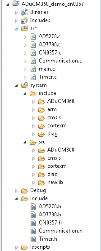
The ADuCM360_demo_cn0357 project use ADuCM36x C/C++ Project structure.
This project contains: system initialization part - disabling watchdog, setting system clock, enabling clock for peripherals; port configuration for SPI1, UART via P0.6/P0.7; SPI, UART read/write functions, AD7790 control, AD5270 control and gas concentration computation.
In the src and include folders you will find the source and header files related to CN0357 software application. The Communication.c/h files contain SPI and UART specific data, the AD7790.c/h files contain the ADC control, the AD5270.c/h files contain the rheostat control and the CN0357.c/h files contain configurations and computations specific to the gas detector application.

In the appropriate header files you can configure next parameters:
#define SENSOR_RANGE 2000
#define SENSOR_SENSITIVITY 65
The system folder contains system related files (try not to change these files):