


This version (14 Mar 2021 09:28) was approved by Zuedmar Arceo.The Previously approved version (14 Jan 2021 05:23) is available.
Table of Contents
Weigh Scale Measurement Demo
The ADuCM360_demo_cn0216 is a weigh scale measurement demo project for the EVAL-ADICUP360 base board with additional EVAL-CN0216-ARDZ shield, created using the CrossCore Embedded Studios Interactive Development Environment(IDE).
General description
This project is a good example for how to use EVAL-ADICUP360 board in different combinations with various shield boards. It expand the list of possible applications that can be done with the base board.
The ADuCM360_demo_cn0216 project uses the EVAL-CN0216-ARDZ shield which is a precision weigh scale system using a 24-bits sigma-delta converter, and auto-zero amplifiers providing high gain for the bridge sensor input

The CN0216 circuit translates the resistance changes on the bridge into very small voltages. The bridge is excited by a regulated 5V and that determines the full scale range of the bridge output. Those values are passed through very low noise, auto zero amplifiers to remove as many error sources as possible before being gained up to levels that will be compatible with the ADC. The 24-bit ADC value is received via SPI interface of the EVAL-ADICUP360 board.

The ADuCM360_demo_cn0216 application processes ADC output value and make all necessary conversions in order to provide the weight results. A UART interface (9600 baud rate and 8-bits data length) is used to send the results to terminal window: ADC Data Register codes, ADC Input Voltage volts, and Sensor Input Weight grams are the outputs provided in the terminal window.
At the start of the project, a calibration of the upper and lower input range of the weigh scale is taken to remove both offset and gain errors in the circuit, providing the most accurate weigh scale measurements possible. Make sure you open up the serial terminal to your PC in order to do the calibration. Once the program is running, it will ask you to make the zero scale calibration, you MUST press <ENTER> to begin the zero scale calibration(takes about 5 seconds). Once that calibration has taken place, the serial terminal will prompt you to add the calibration weight to the scale and then press <ENTER> to make the full scale calibration(again takes about 5 seconds). Those measurements are averaged over 100 samples and then stored into memory as the upper and lower calibration coefficients.
Once calibration is complete, measurements of the output values (weights and conversion information) are displayed every time you press <ENTER> key from the keyboard. Measurements should be between the lower and upper calibration limit can be made at the beginning of the program.
Demo Requirements
The following is a list of items needed in order to replicate this demo.
- Hardware
- EVAL-ADICUP360
- EVAL-CN0216-ARDZ
- Precison Weight Set
- 4- or 6- Wire wheatstone bridge weigh scale ()
- Mirco USB to USB cable
- PC or Laptop with a USB port
- Software
- ADuCM360_demo_cn0216 software
- CrossCore Embedded Studio (2.7.0 or higher)
- ADuCM36x DFP (1.0.2 or higher)
- CMSIS ARM Pack (4.3.0 or higher)
- Serial Terminal Program
- Such as Putty or Tera Term
Setting up the hardware
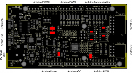
- To program the base board, set the jumpers/switches as shown in the next figure. The important jumpers/switches are highlighted in red.
- Connect the EVAL-CN0216-ARDZ to the Arduino connectors P2, P5, P6, P7, P8 of the EVAL-ADICUP360 board.
- Connect your weigh scale to the EVAL-CN0216-ARDZ via (), make sure you pay attention to the pinout which can be found on the CN0216 hardware page.
- Connect an acceptable 7V-12V power supply into the P11 barrel jack of the EVAL-ADICUP360

Extremely important to plug in an acceptable power supply to the barrel jack P11 for the EVAL-CN0216-ARDZ. The boards will not work if you try only to power it from the DEBUG_USB or the USER_USB.
- Plug in the USB cable from the PC to the EVAL-ADICUP360 base board via the Debug USB.(P14)
Obtaining the Source Code
There are two basic ways to program the ADICUP360 with the software for the CN0216.
- Dragging and Dropping the .Bin to the MBED drive
- Building, Compiling, and Debugging using CCES
Using the drag and drop method, the software is going to be a version that Analog Devices creates for testing and evaluation purposes. This is the EASIEST way to get started with the reference design.
Importing the project into CrossCore is going to allow you to change parameters and customize the software to fit your needs, but will be a bit more advanced and will require you to download the CrossCore toolchain.
The software for the ADuCM360_demo_cn0216 demo can be found here:
Prebuilt CN0216 Bin File
Complete CN0216 Source Files
For more information on importing, debugging, or other tools related questions, please see the tools user guide.
Configuring the Software Parameters
Set the Reference Voltage being used in the AD7791.h file. (in V)
#define VREF 5 /* The board default value is 5V */
Configure the Full Scale Calibration Weight used on the Scale in the CN0216.h file. (in grams)
#define CAL_WEIGHT 1000
Outputting Data
Serial Terminal Output
- In order to view the data, you must flash the program to the EVAL-ADICUP360.
- Once complete you will need to switch the USB cable from the DEBUG USB (P14) to the USER USB (P13).
- Then follow the UART settings below with the serial terminal program.
Following is the UART configuration.
  Select COM Port
  Baud rate: 9600
  Data: 8 bit
  Parity: none
  Stop: 1 bit
  Flow Control: none
- At the start of the project, a calibration of the upper and lower input range of the weigh scale is taken to remove both offset and gain errors in the circuit, providing the most accurate weigh scale measurements possible.
- Make sure you open up the serial terminal to your PC in order to do the calibration. Once the program is running, it will ask you to make the zero scale calibration, you MUST press <ENTER> to begin the zero scale calibration(takes about 5 seconds). Make sure there is NOTHING on the scale.
- Once that calibration has taken place, the serial terminal will prompt you to add the calibration weight to the scale and then press <ENTER> to make the full scale calibration(again takes about 5 seconds). Those measurements are averaged over 100 samples and then stored into memory as the upper and lower calibration coefficients.
- Once calibration is complete, measurements of the output values (weights and conversion information) are displayed every time you press <ENTER> key from the keyboard. Measurements should be between the lower and upper calibration limit can be made at the beginning of the program.
How to use the Tools
The official tool we promote for use with the EVAL-ADICUP360 is CrossCore Embedded Studio. For more information on downloading the tools and a quick start guide on how to use the tool basics, please check out the Tools Overview page.
Importing
For more detailed instructions on importing this application/demo example into the CrossCore Embedded Studios tools, please view our How to import existing projects into your workspace section.
Debugging
For more detailed instructions on importing this application/demo example into the CrossCore Embedded Studios tools, please view our How to configure the debug session section.
Project structure
The ADuCM360_demo_cn0216 project use ADuCM36x C/C++ Project structure.
This project contains: system initialization part - disabling watchdog, setting system clock, enabling clock for peripherals; port configuration for SPI1, UART via P0.6/P0.7; SPI, UART read/write functions; AD7791 control and weight conversions.
In the src and include folders you will find the source and header files related to CN0216 software application. The Communication.c/h files contain SPI and UART specific data, meanwhile the AD7791.c/h files contain the ADC control data and the CN0216.c/h files contain the calibration and measurements management.

The RTE folder contains device and system related files:
- Device Folder – contains low levels drivers for ADuCM360 microcontroller.(try not to edit these files)
- system.rteconfig - Allows the user to select the peripherial components they need, along with the startup and ARM cmsis files needed for the project.
End of Document
resources/eval/user-guides/eval-adicup360/reference_designs/demo_cn0216.txt · Last modified: 14 Mar 2021 09:27 by Zuedmar Arceo