


This version (09 May 2019 15:07) is a draft.
Approvals: 0/1The Previously approved version (07 May 2019 10:40) is available.
Approvals: 0/1The Previously approved version (07 May 2019 10:40) is available.
This is an old revision of the document!
Table of Contents
AD5940_BIA
This demo will use EVAL-ADICUP3029, EVAL_AD5940BIOZ and Impedance-Test board to carry out BIA measurements.
Overview
This example project is designed to carry out body impedance analysis (BIA) measurements. The Impedance Test board is provided with the hardware which models body impedance. It consists of a range of resistors and capacitors which can be used to model body impedance, contact impedance and electrode impedance.
Alternatively, the custom cables can be connected to the body to measure actual body impedance.
Measurement Requirements
The following is a list of items required to carry out the measurement.
- Hardware
- EVAL-ADICUP3029
- EVAL-AD5940BIOZ
- Z-Test Board
- Mirco USB to USB cable
- PC or Laptop with a USB port
- Custom Cables (Optional)
- Software
- AD5940_BIA Example Project (Git Lab)
- Serial Terminal Program, Such as Putty or RealTerm
- IDE such as IAR or Keil
Setting up the Hardware
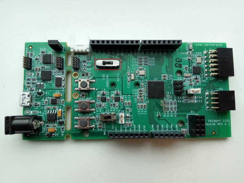
- Set switch S2 to USB Arduino function in order to view data over UART. The UART baud rate is 230400
- Set S5 to Wall/USB to power the board from the USB cable
- Place the EVAL-AD5940BIOZ on top of the EVAL-ADICUP3029.

- Connect the AD5940 Z Test board to the EVAL-AD5940BIOZ board
- All jumpers should be in their default position
- Plug in the micro USB cable into the (P10) USB port on the EVAL-ADICUP3029, and the other end into the PC or laptop.

AD5940 Z Test Board
The AD5940 Z Test board is designed to model skin impedance, body impedance, electrode contact impedance and electrode impedance. There are 5 banks of switches on the board labelled S1, S2, S3, S4 and S5. The function of each bank is described in the following table:
| Switch Bank | Bank Function |
|---|---|
| S1 | Used to model Body Impedance |
| S2 | Used to model contact impedance on F+ electrode |
| S3 | Used to model contact impedance on S+ electrode |
| S4 | Used to model contact impedance on F- electrode |
| S5 | Used to model contact impedance on S- electrode |
The following tables indicate the resistor or capacitor value associated with each switch in the bank. Moving the switch to the ON position connects the corresponding resistor or capacitor value in series on the signal path. If more than one switch is active the corresponding resistor values are connected in series.
| S1 Bank | Corresponding Res/Cap Value |
|---|---|
| S1 | 100 Ω |
| S2 | 200 Ω |
| S3 | 300 Ω |
| S4 | 340 Ω |
| S5 | 510 Ω |
| S6 | 1 kΩ |
| S7 | 2 kΩ |
| S8 | 3.01 kΩ |
| S9 | 4.02 kΩ |
| S10 | 4.99 kΩ |
| S11 | 1000 pF |
| S12 | 0.01 μF |
| S2 Bank | Corresponding Res/Cap Value |
|---|---|
| S1 | 100 Ω |
| S2 | 200 Ω |
| S3 | 300 Ω |
| S4 | 402 Ω |
| S5 | 10 kΩ |
| S6 | 23.7 kΩ |
| S7 | 42.2 kΩ |
| S8 | 42.2 kΩ |
| S9 | 100 kΩ |
| S10 | 200 kΩ |
| S11 | 1000 pF |
| S12 | 0.01 μF |
| S3 Bank | Corresponding Res/Cap Value |
|---|---|
| S1 | 100 Ω |
| S2 | 200 Ω |
| S3 | 300 Ω |
| S4 | 402 Ω |
| S5 | 4.22 MΩ |
| S6 | 4.22 MΩ |
| S7 | 1.43 MΩ |
| S8 | 1 MΩ |
| S9 | 300 kΩ |
| S10 | 300 kΩ |
| S11 | 1000 pF |
| S12 | 0.01 μF |
| S4 Bank | Corresponding Res/Cap Value |
|---|---|
| S1 | 100 Ω |
| S2 | 200 Ω |
| S3 | 300 Ω |
| S4 | 402 Ω |
| S5 | 499 Ω |
| S6 | 1 kΩ |
| S7 | 2 kΩ |
| S8 | 3.01 kΩ |
| S9 | 4.02 kΩ |
| S10 | 4.99 kΩ |
| S11 | 1000 pF |
| S12 | 0.01 μF |
| S5 Bank | Corresponding Res/Cap Value |
|---|---|
| S1 | 100 Ω |
| S2 | 200 Ω |
| S3 | 300 Ω |
| S4 | 402 Ω |
| S5 | 499 Ω |
| S6 | 1 kΩ |
| S7 | 2 kΩ |
| S8 | 3.01 kΩ |
| S9 | 4.02 kΩ |
| S10 | 4.99 kΩ |
| S11 | 1000 pF |
| S12 | 0.01 μF |
AD5940 Z Test Schematic and Layout
Obtaining the Source Code
The source code and include files for the project can be found on Git
Configuring the Software
To compile and run the example open the project in either Keil or IAR. The AD5940BIAStructInit() function configures the main application parameters. These include the sample frequency (BiaODR), and number of samples to feed to DFT block (DFT_Num). Compile the project and download to the hardware.
Outputting Data
The measurement results are sent to the PC via UART. To establish connection over UART, connect the Micro-USB cable to the PC and to the EVAL-ADICUP3029 board. A terminal program such as RealTerm or Putty is required to display the results
Following is the UART configuration.
  Select COM Port
  Baud rate: 230400
  Data: 8 bit
  Parity: none
  Stop: 1 bit
  Flow Control: none
The data on the terminal consists of the Frequency of the excitation signal, the magnitude of the impedance and the phase of the impedance in degrees as in below screenshot.

resources/eval/user-guides/eval-ad5940/software_examples/ad5940_bia.1557407237.txt.gz · Last modified: 09 May 2019 15:07 by Johann Seebeck