


This version is outdated by a newer approved version. This version (03 Jan 2021 22:02) was approved by Robin Getz.The Previously approved version (27 Sep 2019 10:26) is available.
This version (03 Jan 2021 22:02) was approved by Robin Getz.The Previously approved version (27 Sep 2019 10:26) is available.This is an old revision of the document!
Table of Contents
EVAL-AD5593R-PMDZ Overview
EVAL-AD5593R-PMDZ is a minimalist 8-channel, 12-Bit, Configurable ADC/DAC/GPIO with on-chip Reference, I2C interface PMOD module. This boards serve as low-cost alternatives to the full-featured product evaluation boards, with terminal block connections and no extra signal conditioning.

This user guide will focus on the hardware aspect of the EVAL-AD5593R-PMDZ including the connectors, indicators, and different configurations a user would require in order to use the hardware. There are also link to the design files as well as software reference designs that use the hardware with example embedded firmware for a real demo.
Simplified functional block diagram

Connectors and Configuration
The following section reviews all the hardware connectors and how to interface to them. It also reviews configurations options and well as important on board indicators.
Analog/Digital I/O Connector (P2 & P3)
| Connector | Pin No. | Pin Name | Pin Description |
|---|---|---|---|
| P2 | 1 | CH3 | Channel 3 Input/Output |
| 2 | CH2 | Channel 2 Input/Output | |
| 3 | CH1 | Channel 1 Input/Output | |
| 4 | CH0 | Channel 0 Input/Output | |
| 5 | GND | Ground | |
| 6 | VDD | Power Supply | |
| P3 | 1 | VREF | Voltage Reference |
| 2 | GND | Ground | |
| 3 | CH7 | Channel 7 Input/Output | |
| 4 | CH6 | Channel 6 Input/Output | |
| 5 | CH5 | Channel 5 Input/Output | |
| 6 | CH4 | Channel 4 Input/Output |
I2C PMOD Connector (P1)
The EVAL-AD5593R-PMDZ digital IMOD connector is described in the table below.
| Pin No. | Pin Name | Pin Description |
|---|---|---|
| 1 | NC | Not Connected |
| 2 | RST | Reset Pin |
| 3 | SCL | I2C Serial Clock |
| 4 | SDA | I2C Serial Data |
| 5 | DGND | Digital Ground |
| 6 | VDD | Power Supply |
Test Points
User can also check the I2C signal quality and voltage supply of the board using test points labeld RST, SCL, SDA, VLOGIC.

Voltage Reference Configuration
The default connection of AD5593R Vref pin is shorted at pin 1 of JP1 solder jumper where you can easily configure your voltage reference input at pin 1 of terminal block P3, either from external source or internal 2.5V

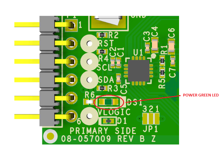
LED Indicator
The DS1 is the power green LED indicator of the board.
More Information and Useful Links
Schematic, PCB Layout, Bill of Materials
Software Examples & Demos
End of Document
resources/eval/user-guides/circuits-from-the-lab/eval-ad5593r-pmdz.1609707365.txt.gz · Last modified: 03 Jan 2021 21:56 by Robin Getz