


This version (05 Sep 2022 07:53) was approved by John Carlo Cillion.The Previously approved version (11 Feb 2021 16:26) is available.
Table of Contents
CN-0383 Hardware and Software User Guide
Overview
CN0383 is a completely integrated 2-wire/3-wire/4-wire resistance temperature detector (RTD) measurement system using a low power, precision, 24-Bit Sigma-Delta ADC optimized for high precision measurement applications. With a two-point calibration and linearization, the overall 3-wire and 4-wire system accuracy is better than ±1°C over a temperature range of −50°C to +200°C and ±1°C accuracy over a temperature range of -50°C to +165°C for 2-wire system.
The AD7124-4 can be configured for 4 differential or 7 pseudo differential input channels, while the AD7124-8 can be configured for 8 differential or 15 pseudo differential channels. The on-chip programmable gain array (PGA) ensures that signals of small amplitude can be interfaced directly to the ADC. The AD7124-4/AD7124-8 establishes the highest degree of signal chain integration, which includes programmable low drift excitation current sources. Therefore, the design of an RTD system is greatly simplified because most of the required RTD measurement system building blocks are included on-chip. The AD7124-4/AD7124-8 gives the user the flexibility to employ one of three integrated power modes, where the current consumption, range of output data rates, and rms noise are tailored with the power mode selected. The current consumed by the AD7124-4/AD7124-8 is only 255 µA in low power mode and 930 µA in full power mode. The power options make the device suitable for non-power critical applications, such as input/output modules, and also for low power applications, such as loop-powered smart transmitters where the complete transmitter must consume less than 4 mA.
The device also has a power down option. In power-down mode, the complete ADC along with its auxiliary functions are powered down so that the device consumes 1 µA typical. TheAD7124-4/AD7124-8 also has extensive diagnostic functionality integrated as part of its comprehensive feature set.
This user guide will discuss how to operate the EVAL-AD7124-4SDZ/EVAL-AD7124-8SDZ (CN-0383 Evaluation Hardware), the EVAL-SDP-CB1Z (SDP-B)/EVAL-SDP-CK1Z (SDP-K1) and the AD7124_EVAL+ Software. A complete design support package for the CN-0383 evaluation material containing schematics, layouts (native and Gerber), and bill-of-materials can be found at: CN0383-DesignSupport.

Required Equipment
- EVAL-AD7124-4SDZ/EVAL-AD7124-8SDZ (CN-0383 Evaluation Hardware)
- EVAL-SDP-CB1Z (SDP-B) or EVAL-SDP-CK1Z (SDP-K1) controller board
- Power supply: USB
- Class B Pt100 2-wire/3-wire/4-wire RTD
- A PC running Windows® with USB 2.0 port
Getting Started
A complete software user guide for the AD7124-4/AD7124-8 and the SDP board can be found in the EVAL-AD7124-4SDZ/EVAL-AD7124-8SDZ user guide and the EVAL-SDP-CB1Z/EVAL-SDP-CK1Z User Guide. Software is required to interface with the hardware. This software can be downloaded from ftp://ftp.analog.com/pub/evalcd/AD7124. If the setup file does not run automatically, double-click setup.exe from the file. Install the evaluation software before connecting the evaluation board and SDP board to the USB port of the PC to ensure that the evaluation system is correctly recognized when connected to the PC. After the evaluation software installation is complete, connect the SDP board (via Connector A) to the EVAL-AD7124-4SDZ/EVAL-AD7124-8SDZ and then connect the SDP board to the USB port of the PC using the supplied cable. When the evaluation system is detected, proceed through any dialog boxes that appear to complete the installation.
General Setup and Test
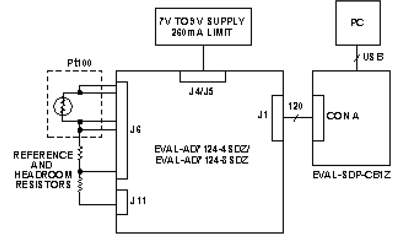
Do not connect power to the hardware until both the EVAL-AD7124-4SDZ/EVAL-AD7124-8SDZ and SDP boards are connected via connector A. Figure below shows a functional block diagram of the test setup for the 2-wire, 3-wire or 4-wire RTD configuration. The EVAL-AD7124-4SDZ/EVAL-AD7124-8SDZ evaluation board is required to test the circuit. In addition, the following sensor and resistors are required for proper operation:
- 2-wire/3-wire/4-wire Pt100 RTD, Class B
- 5.11 kΩ precision resistor
- 250 Ω resistor for buffer headroom (not needed for 3-wire RTD configuration, but included for completeness because it may be required if a Pt1000 RTD is used with a gain of 1)
2-wire RTD
3-wire RTD

4-wire RTD

Hardware Setup
To configure the hardware, take the following steps:
- Set all links on the EVAL-AD7124-4SDZ/EVAL-AD7124-8SDZ to the default board positions as outlined in the EVAL-AD7124-4SDZ/EVAL-AD7124-8SDZ user guide.
- Connect the RTD, precision reference resistor, and resistor for headroom depending on which RTD configuration is using (2-wire/3-wire/4-wire). See figure below.
- For RTD measurements, ensure that the following jumpers are removed.
- LK3 - Jumper from REFIN- to AVss, this jumper should be removed.
- LK4 - This jumper is used to apply external 2.5V or internal 2.5V to REFIN+, this jumper should be removed.
- LK5 - This is the jumper used for the noise test, the function of this jumper is to short AIN0 to AIN1, this jumper should be removed.
- Connect the SDP board to the PC via the USB cable.
Evaluation Board Connector for 2-Wire RTD Measurement

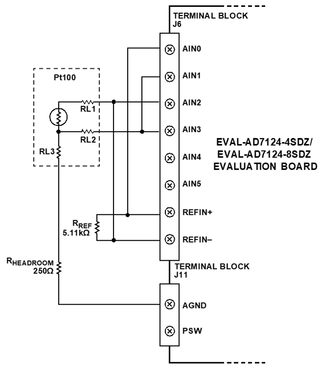
Evaluation Board Connector for 3-Wire RTD Measurement
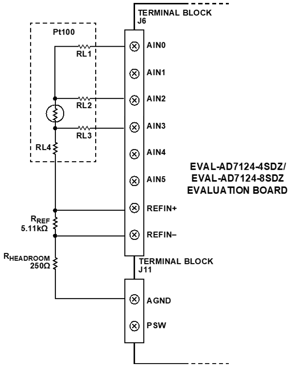
Evaluation Board Connector for 4-Wire RTD Measurement
Using the Evaluation Software
The AD7124_EVAL+ Software interfaces with the EVAL-AD7124-4SDZ/EVAL-AD7124-8SDZ and EVAL-SDP-CB1Z hardware. It can be used to connect to the hardware, configure the ADC, perform a calibrations and execute conversions to evaluate each RTD configuration (CN-0383) reference design.
Run the AD7124_EVAL+ Software, The evaluation software supports both the AD7124-4 and the AD7124-8 devices. On running the software, the user selects the evaluation board that is connected to the PC. For the AD7124-4, select EVAL-AD7124-4SDZ from the drop-down list, as shown in Figure below.

After selecting the Evaluation board, the window shown in Figure below appears.

Demo Mode and ADC Software Configurations
To configure the AD7124-4/AD7124-8 for 2-wire/3-wire/4-wire RTD measurements, click the 2-WIRE RTD/3-WIRE RTD/4-WIRE RTD demo mode button (see Figure above). Clicking the demo mode button configures the ADC software for each RTD configurations. Also, make sure that you follow the instructions indicated in the ![]() beside each RTD configuration.
beside each RTD configuration.
2-WIRE RTD demo mode
To configure the AD7124-4/AD7124-8 for 2-wire RTD measurements, click the 2-WIRE RTD demo mode button. Clicking the 2-WIRE RTD button configures the ADC software as follows:
1. Channel_0:
- AINP_0 = AIN2
- AINM_0 = AIN3
- Setup0
- Enabled = TRUE
2. Setup_0:
- PGA_0 = 16
- AIN_BUFP, AIN_BUFM both = ENABLED
- BIPOLAR = ENABLED
- FS_0 = 384
- FILTER_MODE_0 = SINC4
3. ADC_Control:
- MODE = Continuous Conversion
- POWER_MODE = FULL
4. IO_CONTROL_1:
- IOUT0 Channel Enable = AIN1
- IOUT0 Select = 500 µA
3-WIRE RTD demo mode
To configure the AD7124-4/AD7124-8 for 3-wire RTD measurements, click the 3-WIRE RTD demo mode button. Clicking the 3-WIRE RTD button configures the ADC software as follows:
1. Channel_0:
- AINP_0 = AIN2
- AINM_0 = AIN3
- Setup0
- Enabled = TRUE
2. Setup_0:
- PGA_0 = 16
- AIN_BUFP, AIN_BUFM both = ENABLED
- BIPOLAR = ENABLED
- FS_0 = 384
- FILTER_MODE_0 = SINC4
3. ADC_Control:
- MODE = Continuous Conversion
- POWER_MODE = FULL
4. IO_CONTROL_1:
- IOUT0 Channel Enable = AIN1
- IOUT0 Select = 500 µA
- IOUT1 Channel Enable = AIN1
- IOUT1 Select = 500 µA
4-WIRE RTD demo mode
To configure the AD7124-4/AD7124-8 for 4-wire RTD measurements, click the 4-WIRE RTD demo mode button. Clicking the 4-WIRE RTD button configures the ADC software as follows:
1. Channel_0:
- AINP_0 = AIN2
- AINM_0 = AIN3
- Setup0
- Enabled = TRUE
2. Setup_0:
- PGA_0 = 16
- AIN_BUFP, AIN_BUFM both = ENABLED
- BIPOLAR = ENABLED
- FS_0 = 384
- FILTER_MODE_0 = SINC4
3. ADC_Control:
- MODE = Continuous Conversion
- POWER_MODE = FULL
4. IO_CONTROL_1:
- IOUT0 Channel Enable = AIN1
- IOUT0 Select = 500 µA
Calibrations
One additional step is required before the AD7124-4/AD7124-8 is configured for 2-wire/3-wire/4-wire RTD measurements: an internal full-scale and zero-scale calibration of the AD7124-4/AD7124-8. This calibration can be performed via the Register Map tab, as shown in below.

1. Click the ADC_Control register
2. Select Low Power mode
3. Perform an internal full-scale calibration
- Click the Mode bitfield of the ADC control register
- In the Mode bitfield, select the internal full scale calibration option.
- Check the calibration performed by clicking the Gain0 register from the register tree, and check that the coefficients have changed.
4. Perform an internal zero-scale calibration.
- Click the Mode bitfield of the ADC control register.
- In the Mode bitfield, select the internal zero-scale calibration option.
- Check the calibrations performed by clicking the Offset0 register in the register tree, and check that the coefficients have changed.
5. When calibrations are complete, change the power mode to the required mode of operation, and ensure that the ADC is set to continuous conversion mode by selecting Continuous from the drop-down box in the *Mode* bit field of the ADC_Control register.
RTD Measurements
After calibrations, the board and device can now be configured for 2-wire/3-wire/4-wire RTD measurements as discussed above.
Click the corresponding RTD demo mode and click SAMPLE to start gathering samples from the AD7124-4/AD7124-8. The Waveform tab and the Histogram tab show the data gathered from the AD7124-4/AD7124-8.
Waveform Tab

Histogram Tab

More Information and Useful Links
Schematic, PCB Layout, Bill of Materials
EVAL-CN0383-ARDZ Design & Integration Files
- Schematics
- PCB Layout
- Bill of Materials
- Allegro Project
Software
resources/eval/user-guides/circuits-from-the-lab/cn0383.txt · Last modified: 05 Sep 2022 05:40 by John Carlo Cillion