


This version (29 Jul 2021 07:44) was approved by Harvey John De Chavez.The Previously approved version (25 Jan 2021 11:09) is available.
Table of Contents
CN-0354 Software User Guide
Overview
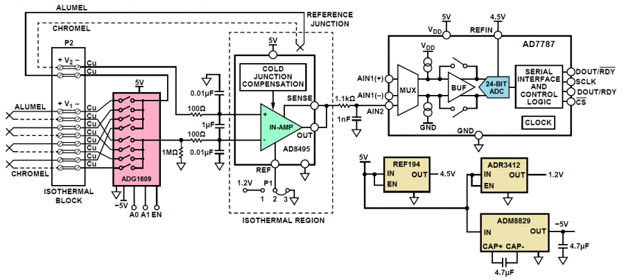
CN-0354 is a flexible, 4-channel, low power thermocouple measurement circuit with an overall power consumption of less than 8 mW. The circuit has a multiplexed front end, followed by an instrumentation amplifier that performs cold junction compensation (0°C to 50°C) and converts the thermocouple output to a voltage with a precise scale factor of 5 mV/°C. The error is less than 2°C, over a measurement range of −25°C to +400°C, and is primarily due to the thermocouple nonlinearity. A nonlinearity correction algorithim reduces the error to less than 0.5°C over a 900°C measurement range. Noise free resolution is less than 0.1°C. The signal is then digitized by a 24-bit Σ-Δ ADC, and the digital value is provided on an I2C serial interface. With the PMOD form factor for rapid prototyping, the design requires minimal PC board area and is ideal for applications that require precise thermocouple temperature measurements.
The four thermocouple inputs to the circuit are terminated at the isothermal block, P2. The ADG1609 CMOS multiplexer switches the four thermocouple channels to a single signal conditioning block to handle four thermocouple inputs.
The signal is amplified by the AD8495, a precision instrumentation amplifier that is laser trimmed to provide a precise 5°mV/°C output for a K type thermocouple. The AD8495 also provides cold junction compensation over a range of 0°C to 50°C.
The fifth thermocouple is added to cancel the voltage generated by any temperature differential that exists between the isothermal block and the AD8495 cold junction compensation circuit.
TheAD7787is a 24-bit, low noise, low power Σ-Δ ADC for low frequency measurement applications, such as thermocouple measurement systems. Its internal clock eliminates the need of an external clock to the device and makes the output data rate user configurable. This can reduce current consumption because it functions at a lower internal clock frequency. It contains a Σ-Δ ADC with one differential input and one single-ended input, either of which can be buffered or unbuffered after passing through a multiplexer.
Required Equipment
- EVAL-SDP-CB1Z Controller Board (SDP-B Board)
- SDP-I-PMOD Interposer Board (SDP-PMOD Interposer Board)
- EVAL-CN0354-PMDZ Evaluation Board (CN-0354 Board)
- EVAL-CFTL-6V-PWRZ +6V Power Supply or equivalent DC Power Supply
- PC with the following minimum requirements
- Windows XP Service Pack 2 (32-bit)
- USB Type-A Port
- Processor rated at 1GHz or faster
- 512 MB RAM and 500 MB available hard disk space
- USB Type-A to USB Mini-B cable
- K-Type Thermocouple millivolt source
- K-Type Thermocouple wire
General Setup
- The EVAL-CN0354-PMDZ (CN-0354 Board) connects to the SDP-I-PMOD Interposer Board (SDP-PMOD Interposer Board) via the 120-pin connector at J3 and is connected to the EVAL-SDP-CB1Z (SDP-B Board) via the 120-Pin connector at J4.
- The EVAL-CFTL-6V-PWRZ +6V power supply powers the EVAL-CN0354-PMDZ (CN-0354 Board) via the DC Barrel Jack of the SDP-I-PMOD Interposer Board (SDP-PMOD Interposer Board) at J1.
- The EVAL-SDP-CB1Z (SDP-B Board) connects to the PC via the USB cable.
- The reference thermocouple connects to the EVAL-CN0354-PMDZ (CN-0354 Board) via the thermocouple connector at +TREF- and the tip of the thermocouple must be placed as close to U4 as possible.
- The thermocouples may be placed at any of the four channels of P2.
NOTE: If not all four thermocouple channels will be used, it is recommended to short out the positive and negative terminal of any unused channel at the isothermal block P2 in order to avoid the AD8495 from railing.

Installing the Software
- Extract the file CN0354 SDP Eval Software.zip and open the file setup.exe.
NOTE: It is recommended that you install the CN-0354 Evaluation Software to the default directory path C:\Program Files\Analog Devices\CN0354\ and all National Instruments products to C:\Program Files\National Instruments\

- Click Next to view the installation review page

- Click Next to start the installation

- Upon completion of the installation of the CN-0354 Evaluation Software, the installer for the ADI SDP Drivers will execute.
NOTE: It is recommended that you close all other applications before clicking “Next”. This will make it possible to update relevant system files without having to reboot your computer.

- Press “Next” to set the installation location for the SDP Drivers.
It is recommended that you install the drivers to the default directory path
C:\Program Files\Analog Devices\SDP\Drivers

- Press “Next” to install the SDP Drivers and complete the installation of all software. Click “Finish” when done.
Using the Evaluation Software
Software Control and Indicator Descriptions

- Start Sampling
- When this button is pressed, the SDP-B Board makes a USB connection to the CN-0354 Board automatically. A connection to the SDP-B Board must be made to use the software. Once a USB connection is established, the software starts sampling in real-time.
- Configure System
- When this button is pressed, the system is configured based on the preferences in the System Configuration tab
NOTE: Default values are provided in the System Configuration tab in order for the software to run even without specified preferences are inputted.
- Save Data
- When this button is pressed, the software will save the data collected to a tab delimited ASCII spreadsheet file.
- Control Tabs
- Start Sampling - Clicking this tab brings the data collection chart to the front.
- Configure System - Clicking this tab brings the system configuration settings to the front.
- SDP Board Information - Clicking this tab brings the SDP Board revision information to the front.
- Thermocouple Channels temperature numerical indicator
- This indicator displays the current temperature measurement in each active channel in degrees Celsius.
- Channel Select checkboxes
- These checkboxes allow for the setting of the active thermocouple channels.
- Chart Controls
- These controls allow the user to zoom-in, zoom-out, and pan through the data collected.
- System Status String and LED Indicators
- This indicator displays the current state of the software in the form of an LED. There are three status LED colors.
 Inactive
 Busy
Busy
 Error
Error

- Temperature Range Dropdown Select
- This control is used to change the temperature range of the system. The default value is 5'C to 880'C.
- Header setting Tab Display
- The tab shows the proper P1 header setting. The red box indicates where the shunt should be placed.
Everytime the temperature range is changed in the software, a corresponding change should be done in the hardware setting as well. Specifically, the P1 header should have the correct setting as showed in the display tab of the Adjust Temperature Range section of the System Configuration Tab.
- Low Calibration Temperature Numerical Control
- This control is used to modify the low calibration temperature setpoint. The greyed out value on the right is the millivolt equivalent of the specified temperature based on the NIST Table for Type K thermocouple.
- The default value is 5°C.
- High Calibration Temperature Numerical Control
- This control is used to modify the high calibration temperature setpoint. The greyed out value on the right is the millivolt equivalent of the specified temperature based on the NIST Table for Type K thermocouple.
- The default value is 880°C.
- Start Calibration
- Pressing this button calibrates the system using the values populated in the calibration temperature numerical controls.
- Calibration Select Dropdown Menu
- The dropdown menu specifies whether to Ignore Calibration where the software ignores the calibration factors derived from the calibaration routine, or to Use Calibration where the software factors in the calibration values in the temperature calculations.
- Update Rate Radio Buttons
- This control is used to change the output word rate of the AD7787. The default value is 16 Hz and is highlighted in bold on the Configure System Tab.
- Buffer Select Radio Buttons
- This control is used to set the mode of the AD7787. The default value is Unbuffered Mode and is highlighted in bold on the Configure System Tab.
- Burnout Current Radio Buttons
- When this control is enabled the 100nA current sources in the signal path are enabled.
The burnout currents can be enabled only when the buffer is active.

Saving Data to a Spreadsheet File
- Establish a USB Connection Link.
- Start Sampling.
- Click the Save Data Button.
- The software automatically opens the Excel spreadsheet file with the data.
The data is exported to an Excel spreadsheet file with columns labeled accordingly.
Registration
Receive software update notifications, documentation updates, view the latest videos, and more when you register your hardware. Register to receive all these great benefits and more!
resources/eval/user-guides/circuits-from-the-lab/cn0354.txt · Last modified: 29 Jul 2021 07:44 by Harvey John De Chavez