


This version (30 Jul 2021 07:26) was approved by Victor Calinao, Jr.The Previously approved version (17 Feb 2021 09:44) is available.
Table of Contents
CN-0251 Software User Guide
Overview
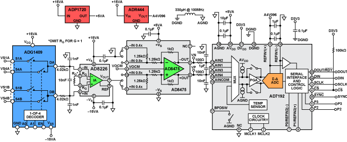
CN-0251 is a flexible signal conditioning circuit for processing signals of wide dynamic range, varying from several mV p-p to 20 V p-p. The circuit provides the necessary conditioning and level shifting and achieves the dynamic range using the internal programmable gain amplifier (PGA) of the high resolution analog-to-digital converter (ADC).
A ±10 V full-scale signal is very typical in process control and industrial automation applications; however, in some situations, the signal can be as small as several mV. Attenuation and level shifting is necessary to process a ±10 V signal with modern low voltage ADCs. However, amplification is needed for small signals to make use of the dynamic range of the ADC. Therefore, a circuit with a programmable gain function is desirable when the input signal varies over a wide range.
In addition, small signals may have large common-mode voltage swings; therefore, high common-mode rejection (CMR) is required. In some applications, where the source impedance is large, high impedance is also necessary for the analog front-end input circuit.
This user guide will discuss how to use the evaluation software to collect data from the EVAL-CN0251-SDPZ Evaluation Board (CN-0251 Board)
Required Equipment
- EVAL-SDP-CB1Z Controller Board (SDP-B Board)
- EVAL-CN0251-SDPZ Evaluation Board (CN-0251 Board)
- +6V Power Supply
- ±15V Dual Power Supply
-
- PC with the following Minimum Requirements
- Windows XP Service Pack 2 (32-bit)
- 2xUSB Type A Port
- Processor rated at 1GHz or faster
- 512 MB RAM and 500 MB available hard disk space
- USB Type A to USB Mini-B cable
- USB Type A to USB Micro-B cable
General Setup
- The EVAL-CN0251-SDPZ (CN-0251 Board) connects to the EVAL-SDP-CB1Z (SDP-B Board) via the 120-Pin connector at J5.
- The +6V Power Supply powers the EVAL-CN0251-SDPZ (CN-0251 Board) via the screw terminals at J3.
- The ±15V Dual Power supply powers the EVAL-CN0251-SDPZ (CN-0251 Board) via the screw terminals at J4.
- The EVAL-SDP-CB1Z (SDP-B Board) connects to the PC via the USB Type A to USB Mini-B cable.
- The ADALM2000 connects to the PC via the USB Type-A to USB Micro-B cable.

Connecting the Hardware
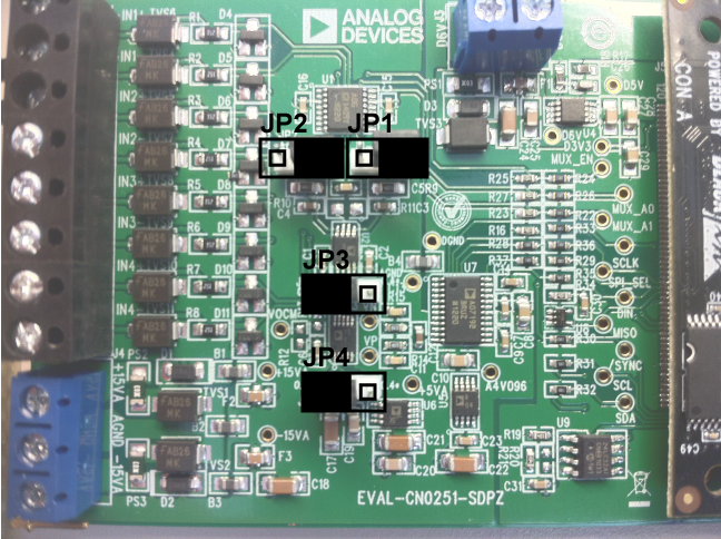
- Ensure the jumpers are populated on the EVAL-CN0251-SDPZ (CN-0251 Board) as depicted in the figure below.
- JP1 and JP2 configure the analog inputs for single-ended or differential inputs
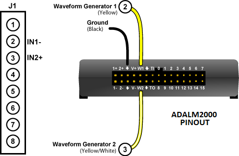
- Connect the ADALM2000 to the EVAL-CN0251-SDPZ (CN-0251 Board) as depicted in the figures below.
- The waveform outputs should be connected to J1:2 (IN1-) and J1:3 (IN2+) of the CN-0251 Board.
- Connect the +6V Power Supply to the screw terminal at J3.
- Connect the ±15V Power Supply to the screw terminal at J4.
- Connect the SDP-B Board to the CN-0251 Board

Getting Started with ADALM2000 and Scopy
- Upon connecting the ADALM2000 to Scopy, load the project file named SigGen.ini then click on the Signal Generator tab on the left pane.

- Click the Run button.


Using the Evaluation Software
Software Control and Indicator Descriptions

- Connect/Reconnect Button
- When this button is pressed, the SDP-B Board makes a USB connection to the CN-0288 Board. A connection to the SDP-B Board must be made to use the software.
- Capture Data Button
- When this button is pressed, the SDP-B Board will collect conversion data and present the acquisitions in the chart.
- Save Data Button
- When this button is pressed, the software will save the data collected to a tab delimited ASCII spreadsheet file.
- Control Tabs
- Data - Clicking this tab brings the data collection chart to the front.
- Analysis - Clicking this tab brings the data analysis histogram to the front.
- Configure System - Clicking this tab brings the system configuration control to the front.
- SDP Board Information - Clicking this tab brings the SDP Board Information indicators to the front.
- Input Channel Drop-Down Menu
- Clicking this drop-down menu selects the channel to capture data from.
- Input Range Drop-Down Menu
- Clicking this drop-down menu selects the analog input voltage range for the channel selected by the Input Range Drop-Down Menu.
- AD8475 Gain Indicator
- This indicator displays the gain setting required from the AD8475.
Jumpers JP3 and JP4 on the EVAL-CN0251-SDPZ (CN-0251 Board) must be populated to reflect the value displayed by this indicator
- AD7192 Gain Indicator
- This indicator displays the gain currently programmed into the AD7192.
- Samples to Capture Control
- This numerical control sets the number of samples to capture once the Capture Data Button is pressed.
- Display Unit Drop-Down Menu
- Clicking this drop-down menu allows you to select chart y-axis units to display.
- Chart Controls
- These controls allow the user to zoom-in, zoom-out, and pan through the data collected.
- System Status String Indicator
- This indicator displays a message to the user detailing the current state of the software.
Establishing a USB Connection Link
- Follow the instructions to properly install the software and connect the hardware as described in the previous sections.
- Open the file named CN0251.exe in the installation directory.
NOTE: If the software was installed to the default location it will be found at
C:\Program Files\Analog Devices\CN0251\CN0251.exe
- Click the Connect/Reconnect Button. A window with a progress bar will load.
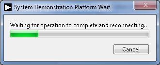
- Upon success, the System Status String Indicator will display Ready to Capture Data
Capturing Data
- Establish a USB Connection Link.
- Click the Input Channel Drop-Down Menu to select the channel to convert
- Click the Input Range Drop-Down Menu to select the range of the analog input voltage.
Changing this control will change the AD8475 Gain Indicator. Please ensure that JP3 and JP4 on the EVAL-CN0251-SDPZ (CN-0251 Board) are populated to reflect the gain displayed by the AD8475 Gain Indicator.
- Input the number of samples to capture into the Samples to Capture Control
- Click the Capture Data Button and wait until acquisition is complete.

Changing the Display Units
- Click the Display Unit Drop-Down Menu to select the units to display.
Saving Data to a Spreadsheet File
- Establish a USB Connection Link.
- Capture Data.
- Click the Save Data Button.
- Browse to the directory location where the spreadsheet file is to be saved.
- Name the file.
- Click the OK Button.
The software saves the spreadsheet file as ASCII text with columns separated by tabs.
Registration
Receive software update notifications, documentation updates, view the latest videos, and more when you register your hardware. Register to receive all these great benefits and more!
End of document
resources/eval/user-guides/circuits-from-the-lab/cn0251.txt · Last modified: 30 Jul 2021 07:26 by Victor Calinao, Jr