


This version is outdated by a newer approved version. This version (19 Apr 2018 09:50) is a draft.
Approvals: 0/1
This version (19 Apr 2018 09:50) is a draft.Approvals: 0/1
This is an old revision of the document!
Table of Contents
CN0194 Software User Guide
Overview
CN0194 provides galvanic isolation for high speed, high accuracy, simultaneous sampling analog-to-digital conversion applications. The AD7685 is a 16-bit, charge redistribution successive approximation (SAR) analog-to-digital converter (ADC) that operates from a single VDD power supply from 2.3V to 5.5V. It contains a low power, high speed, 16-bit sampling ADC with no missing codes, no pipeline delay, an internal conversion clock, and a versatile serial interface port. The ADC also contains a low noise, wide bandwidth, short aperture delay, track-and-hold circuit. The AD7685 PulSAR ADC is versatile and allows monitoring of multiple channels through daisy chaining.

Required Equipment
- EVAL-SDP-CB1Z Evaluation Board (SDP-B Board)
- EVAL-CN0194-SDPZ Evaluation Board (CN-0194 Board)
- Power Supply
- Adjustable DC power supply, output should satisfy: from +6V to +12V over than 500mA.
- 6 to 12V DC wall wart.
- USB Type-A plug to USB Mini-B plug cable
- PC with the following
- Microsoft Windows 7 with sp1 x86 or x64 version, or later
- Intel Core processor (x86 or x64 compatible), 2GHz or faster
- At least 4GB RAM and 8GB available hard disk space
- .NET Framework 4.5 or later
- SDP EEPROM Programmer software
- Supplied with CD
- CN0194 Programming File
- Supplied with CD
- CN0194 SDP Evaluation Software
- Supplied with CD
General Setup
- The EVAL-CN0194-SDPZ (CN-0194 Board) connects to the EVAL-SDP-CB1Z (SDP-B Board) via the 120-Pin connector CON A
- Use the Adjustable DC power supplies to powers the EVAL-CN0194-SDPZ (CN-0194 Board) via the J4 connector
- The EVAL-SDP-CB1Z (SDP-B Board) connects to the PC via the USB cable.
Connecting the Hardware
Installing the Software
- Extract the file CN0194_Evaluation_Software.zip and open the file setup.exe.
NOTE: It is recommended that you install the CN0194_Evaluation_Software.zip to the default directory path C:\Program Files\Analog Devices\ (in 32-bit operational system) or C:\Program Files (x86)\Analog Devices\ (in 64-bit operational system), and all National Instruments products to C:\Program Files\National Instruments\ (in 32-bit operational system) or C:\Program Files (x86)\National Instruments\ (in 64-bit operational system)

- Click Next to view the installation review page
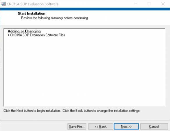
- Click Next to start the installation, after the installation, the installer for the ADI SDP Drivers will execute.

- Press “Next” to set the installation location for the SDP Drivers.
It is recommended that you install the drivers to the default directory path
C:\Program Files\Analog Devices\SDP\DriversR2\ (in 32-bit operational system) or C:\Program Files (x86)\Analog Devices\SDP\DriversR2\ (in 64-bit operational system)

- Press “Next” to install the SDP Drivers and complete the installation of all software. Click “Finish” when done.

Using the Evaluation Software
Software Control and Indicator Descriptions
- Connect/Disconnect Button
- When this button is clicked, the SDP-B Board USB connection to the CN-0194 Board status will be filliped. A connection to the SDP-B Board must be made to use the software.
- Capture Data Button
- When this button is pressed, the SDP-B Board will collect conversion data and present the acquisitions in the chart.
- Save Data Button
- When this button is pressed, the acquired data will be saved (edit).
- Sample Rate Setting
- The speed at which the ADC will convert.
- Samples Setting
- The number which input to this box is use to set the samples for each time the capture data button pressed.
- Channel Display
- Sets which channel is used and displayed.
- Control Tabs
- Time Domain : This Tab showing the acquired data analyzed result in histogram.
- Frequency Domain : This Tab include two indicators to showing the position and velocity output of RDC, update in real time when RDC is converting.
- Histogram :
- S/W Version Info : Showing the SDP-B Board information when USB connection available.
- Navigation Tools
- Cursor :
- Magnification : Contains magnification tools
- Hand : Used for navigating through the graph
- Axis Tools
- Text Box : Provides easy graph navigation
- Lock : Enables/Disables auto scroll of the graph
- Settings : Conatains axis settings
- SDP Status String Indicator
- This indicator displays a message regarding the status of the SDP-B Board.
- Status LED
- This LED showing the ADC working status, when ADC is converting this LED will be light up, otherwise it will be turn off.
- Frequency Analysis
- THD : Total harmonic distortion
- SNR : Signal to noise ratio in decibels
- SINAD : Signal over noise and amplitude distortion
- SFDR : Spurious free dynamic range
- Sin/N : Signal over noise power
- Noise floor : Noise power level
- Fund ampl : Amplitude of fundamental frequency
- Fund Freq : Fundamental frequency of the signal
- SDP Firmware Revision Details
- Major Rev:
- Minor Rev:
- Date:
- Host Code Rev:
- BF Code Rev:
- Time: *
Establishing a USB Connection Link
- Follow the instructions to properly install the software and connect the hardware as described in the previous sections.
- Open the file named CN0194.exe in the installation directory.
NOTE: If the software was installed to the default location it will be found at
C:\Program Files\Analog Devices\CN0194\CN0194.exe (in 32-bit operational system) or C:\Program Files (x86)\Analog Devices\CN0194\CN0194.exe (in 64-bit operational system)
- Click the Connect Button. A window with a progress bar will load.

- Upon success, the System Status String Indicator will display SDP Board serial number
Capturing Data
- Establish a USB Connection Link.
- Set the preferred sample rate, samples and channel.
- Click the Capture Data Button.
- When the number of samples reached the samples setting the converting will stop.
- Click the Save Data Button to save the conversion data.
resources/eval/user-guides/circuits-from-the-lab/cn0194.1524124241.txt.gz · Last modified: 19 Apr 2018 09:50 by Jesse Daniel Santos