X-Band Developer's Kit Block Diagram
Required Peripherals
Digital
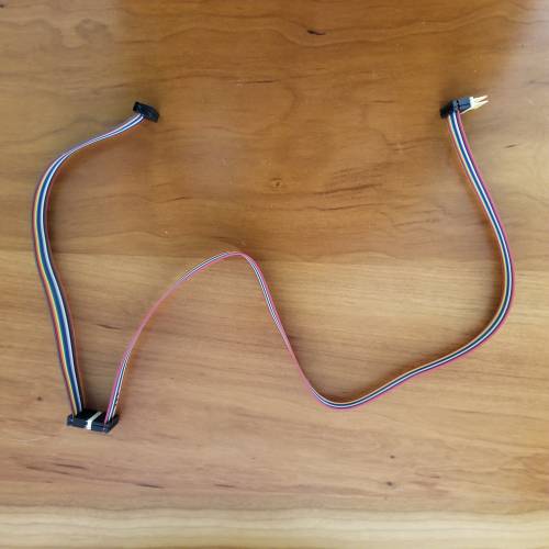
4x PMOD ribbon cables, length depends on desired setup, but the total length of each combined PMOD cable will need to be at least 20“ (50cm). You need 2x cables for
each Stingray PMOD connection as the ZCU102's PMOD pinout orientation doesn't directly match that of the Stingray board. You can use any 12-pin cable compatible with PMOD headers.
Note that the Stingray board includes 2x cables already (
IDSD-06-D-08.00-T). One example part number for the second set of cables:
IDSD-06-D-1200. (12” long, using these 2 cables together creates a 20“ cable).

12-pin male-male adapters to connect PMOD cables to each other and to the ZCU102/Stingray. Quantity depends on the gender of the cables used. Both Stingray connectors are female, while on the ZCU102, one PMOD connector is male and the other female. Note that the Stingray board includes 4x of these.
One example part number:
TSW-106-08-G-D.
FMC riser to raise the MxFE board and allow access to the HPC1 connector for XUD1a control.
FMC extension used to extend access to the HPC1 connector for XUD1a control.
RF Connectors
The Stingray board uses SMPM connectors on both sides of the board, so depending on how the board is used, adapters to mate with test equipment cabling may be required. Note that the Stingray board includes 1x 12” SMPM-SMA cable.
One example adapter cable:
SMPM to SMA Adapter Cable The XUD1a board uses SMA connectors on the RF side of the board and SMPM connectors on the IF side of the board. Note that the XUD1A board includes 1x 12“ SMPM-SMA cable.
The MxFE board uses SMA connectors for both the ADCs and DACs.
Board Connections to the ZCU102
Stingray: ADAR1000-EVAL1Z
Connect the Stingray board to the PMOD connectors on the ZCU102 as described below:
J55 from the ZCU102 should connect to P3 on the Stingray board using a ribbon cable and any required adapters. Note that pin 1 should connect to pin 1. This will require two PMOD cables to vertically flip the pinout from the ZCU102 to match that of the Stingray board.
J87 from the ZCU102 should connect to P4 on the Stingray board using a ribbon cable and any required adapters. Note that pin 1 should connect to pin 1. This will require two PMOD cables to vertically flip the pinout from the ZCU102 to match that of the Stingray board.

XUD1a: ADXUD1AEBZ
Connect the XUD1a evaluation board to the ZCU102's HPC1 port. The FMC extension is used both to move the interposer board and XUD1a away from the MxFE evaluation board as well as to allow access to the HPC1 connector which is otherwise blocked by the MxFE evaluation board.

MxFE: AD9081-FMCA-EBZ
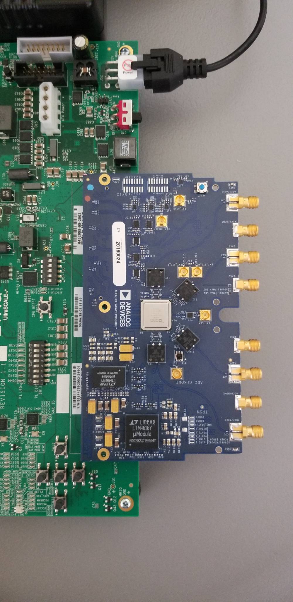
Connect the MxFE evaluation board to the ZCU102's HPC0 port as shown below.
Don't forget to use the use the
FMC riser to raise the AD9081 up!

Inter-Board Connections
MxFE to XUD1a
Connect the MxFE and XUD1a together using SMA-SMPM cables as indicated below:
| Connection # | MxFE Connector | XUD1a Connector |
| 1 | ADC3 (SMA) | J10 (SMPM) |
| 2 | ADC1 (SMA) | J8 (SMPM) |
| 3 | DAC3 (SMA) | J9 (SMPM) |
| 4 | DAC2 (SMA) | J7 (SMPM) |
| 5 | DAC1 (SMA) | J5 (SMPM) |
| 6 | DAC0 (SMA) | J1 (SMPM) |
| 7 | ADC0 (SMA) | J6 (SMPM) |
| 8 | ADC2 (SMA) | J2 (SMPM) |
XUD1a to Stingray
The XUD1a has 4 RFIO ports whereas the Stingray board has 8. For this system, the Stingray's 8 channels will be paired using external splitter/combiners (Recommended Splitter/Combiner) to create 4 digital channels which can interface with the XUD1a and MxFE. The below tables show how these connections are to be made.
| Connection # | Stingray Connectors | Splitter # (Ports 1/2) |
| 1 | J1, J3 (SMPM) | 1 (SMA) |
| 2 | J2, J4 (SMPM) | 2 (SMA) |
| 3 | J6, J8 (SMPM) | 3 (SMA) |
| 4 | J5, J7 (SMPM) | 4 (SMA) |
| Connection # | XUD1a Connector | Splitter # (Sum Port) |
| 1 | J1D (SMA) | 1 (SMA) |
| 2 | J1C (SMA) | 2 (SMA) |
| 3 | J1B (SMA) | 3 (SMA) |
| 4 | J1A (SMA) | 4 (SMA) |
Support

