


This version is outdated by a newer approved version. This version (07 May 2021 19:41) was approved by Jude Osemene.The Previously approved version (07 May 2021 14:24) is available.
This version (07 May 2021 19:41) was approved by Jude Osemene.The Previously approved version (07 May 2021 14:24) is available.This is an old revision of the document!
Table of Contents
EV-ADF5610SD1Z ACE SOFTWARE USER GUIDE
Software Installation Procedures
You can install the EV-ADF5610SD1Z plug-in from the ACE start-up page.
- You can install ACE from http://www.analog.com/en/design-center/evaluation-hardware-and-software/ace-software.html.
- On the ACE start-up page locate and click the Plug-in Manager on the Side bar.
- Search for Board.ADF5610 and install plug-in
Evaluation Board Set-up
To run the plug-in, perform the following steps:
- After installation, double click the ADF5610 icon that appears on the Attached Hardware tab when the SDP board is connected and attached to the board. If the icon does not appear, consider re-installing the ADF510 plug-in or try refreshing Attached hardware icon.
- Connection is automatically established with the SDP-S when you navigate into the front panel of the Board plug-in
 Figure 1: Attached Hardware Tab
GENERAL SOFTWARE FEATURES
Main Controls
The RF Output Controls tab (see figure 2) contains the RF settings for control of the output frequency. Consult the register descriptions for the ADF5610 datasheet for details. Ensure that the value of the External Reference Frequency box equals the applied reference signal. The External Reference Frequency is set to 50MHz by default, which is the frequency of the on-board reference source. The PFD frequency is calculated from the reference frequency, the R counter, the reference doubler, and the reference divide by 2. Ensure that the value in the f_PFD (MHz) box matches the value specified in the loop filter design.
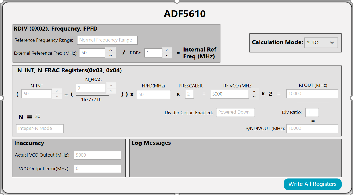 Figure 2: Main Controls tab
General Controls
The General Controls tab (see Figure 3) contains the other register settings, as described in the ADF5610 data sheet.
 Figure 3 : General Controls
VCO Subsystems Controls
The VCO Subsystems controls lets you set the VCO register parameters, as described in the ADF5610 data sheet. There is also a section in the VCO subsystems tab to readback subbands of the current frequency by a simple button click. The subband values are returned for the current RF VCO frequency when Read Subband is pressed.
 Figure 4: VCO Subsystem with Read Subband Register Tab
Sweep and Hop Controls
Sweep and Hop Control lets you perform Sweep or Hop when Autocalibration is enabled or disabled.
Sweep
- To sweep between frequencies with Autocalibration enabled, first define start VCO frequency, stop VCO frequency and channel spacing. This will start sweep using the frequencies while the Autocalibration subband table is populated with the sweep frequencies and subbands.
- To sweep using subbands, the Autocalibration Subbands table must be populated with the subbands from Autocalibration sweep. When Autocalibration is disabled and sweep is started, sweep will be use the subbands on the Autocalibration Subbands table.
Autocalibration Subbands Table
There are three buttons on the top righthand corner of the Autocalibration subband table used to control the data contained in the table.
- The first button is used to import subband data saved in csv file stored in the local directory.
- The second button icon is used to export a copy of the subband data in csv format in a local directory.
- The third button is used to add a single sweep step to the table using the current VCO start frequency.
The Autocalibration subbands table can be cleared using the clear table button under the table. Finally, a subband sweep can be performed at random by using the delete icon on each column to delete a sweep step or define a VCO start frequency and use the add button to add the sweep step to the table.
Hop
Similar to the Sweep, you can hop between two frequencies.
- When Autocalibration is active, it automatically calibrates the subband needed for that particular frequency.
- For frequency hop in manual mode, run Autocalibrate using the Calibrate button to obtain the start and stop subbands. These subbands are pre-loaded into subbands A and B field, and Autocalibration is deactivated. Frequency hop is then executed with the known subbands loaded into the device.
 Figure 5: Sweep and Hop tab
EVALUATION AND TEST
To evaluate and test the performance of the EV-ADF5610SD1Z use the following procedure. To ensure the software is able to program the device correctly, follow these few steps as they appear anytime the board is powered up.
- Connect the USB cable from the SDP-S board.
- Connect the 6V power supply to the VCC 6.1V SMA (J7) connector, but ensure power supply is turned off.
- Connect the USB cable from the SDP-S board to the PC
- Run the ACE software.
- Select ADF5610 that appears on the Attached Hardware connection tab and navigate to the main controls of the ADF5610.
- Power the 6V power supply.
- Connect the spectrum analyzer to SMA Connector RFOUT (J1).
- If the board is configured for external reference, connect the reference to the SMA Connector REFIN (J4). Ensure the external reference match the value on the software main control.
- Click Write All Registers in the bottom right corner of the RF Control tab.
- Measure the output spectrum and single sideband phase noise.
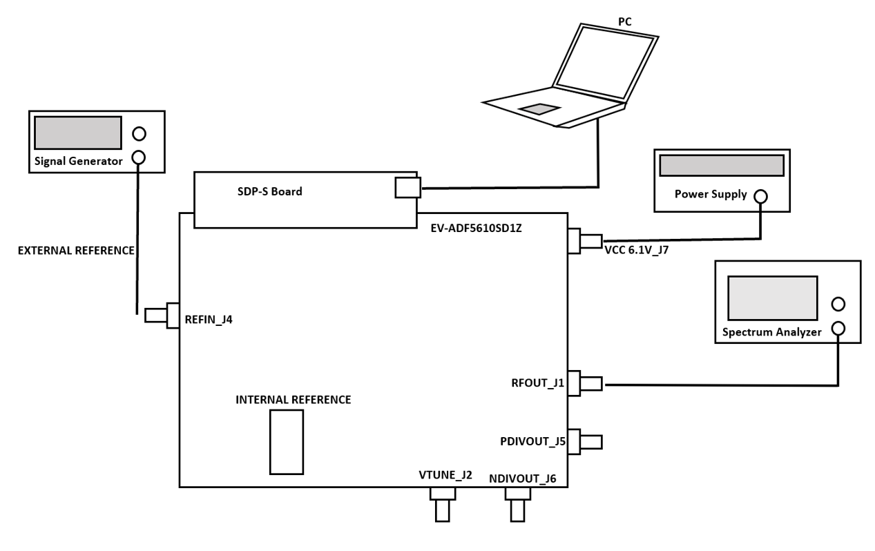 Figure 6: Device Setup procedure
Read Subband Register
You should attempt to read subband only when Autocalibration is enabled. This is because the Subband Register is updated when Autocalibration is enabled before navigating to desired frequency:
- Select desired VCO frequency you want to read subband and Apply Changes.
- Navigate to the VCO Subsystem tab and hit the readback subband button.
resources/eval/adf5610-ace-software-guide.1620409279.txt.gz · Last modified: 07 May 2021 19:41 by Jude Osemene