


This version (11 Feb 2019 02:03) was approved by Patrick Errgy Pasaquian.The Previously approved version (30 Jan 2015 14:54) is available.
Table of Contents
EVALUATING THE AD9625 ANALOG-TO-DIGITAL CONVERTER
INTRODUCTION
This user guide describes the AD9625 evaluation board, AD9625-2.5EBZ, which provides all of the support circuitry required to operate this part in the various modes and configurations. The application software used to interface with the device is also described.
The AD9625 data sheet provides additional information and should be consulted when using the evaluation board. All documents and software tools are available at www.analog.com/hsadcevalboard. For additional information or questions, send an email to highspeed.converters@analog.com.
The AD9625 is a 12-bit ADC with sampling speeds of up to 2500 MSPS. It is designed to support wideband applications where high sample rates, small size, wide bandwidth and versatility are desired. The ADC core features a multistage, differential pipelined architecture with integrated output error correction logic. This reference design includes the device data capture board via the JESD204B serial interface and the SPI interface. The samples are written to the internal memory on the FPGA capture board. It allows programming the device and monitoring its internal registers via SPI.
FEATURES
- Full featured evaluation board for the AD9625
- SPI interface for setup and control
- Balun input drive option
- On-board Power Supply options: Switcher only, Switcher + LC Filter, Switcher + LDO regulator
- VisualAnalog® and SPI controller software interfaces
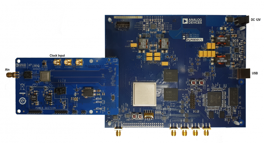
Figure 1. AD9625 Evaluation Board Connection—AD9625-2.5EBZ (on Left) and HSC-ADC-EVALEZ (on Right)
REQUIRED HARDWARE
- AC to 12V DC power supply
- Analog signal source, anti-aliasing filter and SMA cable.
- Analog Clock source and SMA cable.
- PC running Windows
- USB 2.0 cable
- AD9625 Evaluation Board
- HSC-ADC-EVALEZ FPGA Based Data Capture Board
DESIGN AND INTEGRATION FILES
- Schematics:
- RevA: 9625ce04c1_sch.pdf
- Board File:
- RevA: 9625ce04c1-1-24.zip
- BOM:
- Analog Input S-Parameter Model, ad9625_input_model.zip
HELPFUL DOCUMENTS
- AD9625 data sheet http://www.analog.com/AD9625
- AD9625 Evaluation Board “Quick Start User Guide”:
- * High Speed ADC Capture Evaluation Kit Rev E (HSC-ADC-EVALEZ) http://wiki.analog.com/resources/eval/hsc-adc-evale
- AN-905 Application Note, VisualAnalog Converter Evaluation Tool Version 1.0 User Manual
- AN-878 Application Note, High Speed ADC SPI Control Software
- AN-877 Application Note, Interfacing to High Speed ADCs via SPI
- AN-835 Application Note, Understanding ADC Testing and Evaluation
- Power by Linear Journal: “Silent Switcher uModule Regulators Quietly Power GSPS Sampling ADC in Half the Space” https://www.analog.com/media/en/technical-documentation/lt-journal-article/PbLJournal-V1N3-2018-08-RevA.pdf
EASY START Steps
Important Note Administrative rights for the Windows operating systems are needed during the entire software installation procedure. Completion of every step before reverting to a normal user mode is recommended.
1. Download and Install VisualAnalog. For the latest updates to the software, check the Analog Devices website at High Speed ADC Eval Boards.
2. Connect the ADC evaluation board to the ADC capture board. Insert the 12V wallwart adapter to the ADC capture board. The ADC capture board will provide power to the ADC evaluation board through the FMC connector.
3. Connect the provided USB cable to the ADC capture board and to an available USB port on the computer.
4. The ADC capture board is supplied with a wall mount switching power supply. Connect the supply end to an ac wall outlet rated for 100 Vac to 240 Vac at 47 Hz to 63 Hz. The other end is terminated with a plug that connects to the PCB at P1301. The supply is fused and conditioned before connecting to the regulators that supply the proper bias to the entire HSC-ADC-EVALEZ capture board.
5. Once the USB cable is connected to both the computer and the HSC-ADC-EVALEZ board, and power is applied, the USB driver starts to install. The Found New Hardware Wizard opens and prompts you through the automated install process.
6. (Optional) Verify in the Windows device manager that Analog Devices HADV6-FMC is listed under the USB hardware.
7. Make sure the evaluation boards are powered on before connecting the analog input and clock. Connect the appropriate analog input (which should be filtered with a band-pass filter) and low jitter clock signal.
8. Refer to the VisualAnalog User Manual at High Speed ADC Eval Boards for detailed software operating instructions.
eval/ad9625.txt · Last modified: 08 Feb 2019 08:20 by Patrick Errgy Pasaquian