Wiki

This version is outdated by a newer approved version.DiffThis version (31 Jul 2017 05:19) was approved by Dann Kristofer Bautista, Antoniu Miclaus.The Previously approved version (31 Jul 2017 03:02) is available.Diff

This is an old revision of the document!


Signal Generator - Test Case

Initial Setup

In order to proceed through the test case, first of all delete the Scopy *.ini file (saves previous settings made in Scopy tool) from the following path on Windows: C:\Users\your_username\AppData\Roaming\ADI .

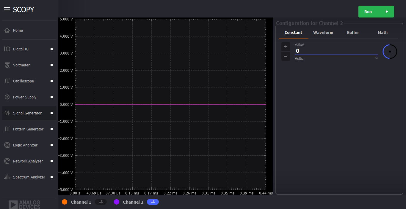
Open the Signal Generator instrument. The interface should look like the picture below:

Press multiple times on the “Run” button to check if the instrument works.

Test Title


A. Channel 1 Operation

Click to display ⇲

Click to hide ⇱

Description Test Steps Steps Resources Expected Results
Testing the constant voltage generator 1. Turn on channel 1 and view the configuration window by clicking the on/off button and menu button respectively. Choose Constant from the configuration menu The interface should look like in the “Step Resources” picture (left side)
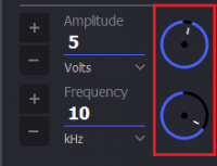
Checking increment/decrement value; ±1V 2. Set the knob to ± 1V interval. No orange dot on the center. The interface should look like in the “Step Resources” picture (left side)
3. Change the voltage value using the up and down arrow The voltage value should change accordingly with an increment or decrement of ±1V from -5V to 5V. The graphical representation should follow accordingly
Checking increment/decrement value; ±100mV 4. Set the knob to ± 100mV interval. With orange dot on the center. The interface should look like in the “Step Resources” picture (left side)
5. Change the voltage value using the up and down arrow The voltage value should change accordingly with an increment or decrement of ±100mV from -5V to 5V. The graphical representation should follow accordingly
6. Connect AWG ch1 to scope ch1+ and scope ch1- to gnd
7. Set the voltage value of the signal generator to 4.5V and set the Oscilloscope’s Volts/div from 1V/div to 5V/div and set the trigger mode to auto. The voltage reading on the oscilloscope should be from 4.4V to 4.6V using the cursor or from the measured data
8. Set the voltage value of the signal generator to -4.5V and set the Oscilloscope’s Volts/div from 1V/div to 5V/div and set the trigger mode to auto. The voltage reading on the oscilloscope should be from -4.4V to -4.6V using the cursor or from the measured data
Testing different waveform types 1. Turn on channel 1 and view the configuration window by clicking the on/off button and menu button respectively. Choose Waveform from the configuration menu The interface should look like in the “Step Resources” picture (left side)
Checking increment/decrement value of Amplitude and Frequency; Large increment 2. Set the knob to without the orange dot on the center. The interface should look like in the “Step Resources” picture (left side)
3. Change the Amplitude or Frequency value using the up and down arrow The amplitude value should change accordingly with a high increment/decrement from 1uV to 10V. The frequency value should change accordingly with a high increment/decrement from 1mHz to 20MHz.The graphical representation should follow accordingly
Checking increment/decrement value of Amplitude and Frequency; ±1 unit on least significant digit 4. Set the knob to with the orange dot on the center. The interface should look like in the “Step Resources” picture (left side)
5. Change the voltage or frequency value using the up and down arrow The Amplitude value should change accordingly with a ±1 unit on the least significant digit from 1uV to 10V. The frequency value should change accordingly with a ±1 unit on the least significant digit from 1mHz to 20MHz.The graphical representation should follow accordingly
Checking increment/decrement value of the Offset and Phase; ±1V and ±1° 6. Set the knob without the orange dot on the center. The interface should look like in the “Step Resources” picture (left side)
7. Change the Offset voltage or Phase value using the up and down arrow The Offset voltage value should change accordingly with ±1 increment/decrement from -5V to 5V. The phase value should change accordingly with a ±1 increment/decrement from 0° to 360°.The graphical representation should follow accordingly
Checking increment/decrement value of Offset voltage and Phase; ±100mV and ±0.1° 8. Set the knob to with the orange dot on the center. The interface should look like in the “Step Resources” picture (left side)
9. Change the Offset voltage or Phase value using the up and down arrow The Offset voltage value should change accordingly with ±.1 increment/decrement from -5V to 5V. The phase value should change accordingly with ±.1 increment/decrement from 0° to 360°.The graphical representation should follow accordingly
10. Connect AWG ch1 to scope ch1+ and scope ch1- to gnd
11. Set the signal generator’s waveform type: Sinewave, Amplitude 2V, Frequency: 200Hz, offset: 0V and Phase: 0 degrees. Set the Oscilloscope’s Volts/div: 500mV/div, trigger mode: Auto and time base: 5ms. The measurement reading on Oscilloscope should be: Period: 5ms, Frequency: 200Hz, Peak-peak: 1.9V to 2.1V
12. Set the signal generator’s waveform type: Sinewave, Amplitude 2V, Frequency: 5MHz, offset: 0V and Phase: 0 degrees. Set the Oscilloscope’s Volts/div: 500mV/div, trigger mode: Auto and time base: 200ns The measurement reading on Oscilloscope should be: Period: 200ns, Frequency: 5MHz, Peak-peak: 1.9V to 2.1V
13. Set the signal generator’s waveform type: Square wave, Amplitude 5V, Frequency: 200Hz, offset: 0V and Phase: 0 degrees. Set the Oscilloscope’s Volts/div: 1V/div, trigger mode: Auto and time base: 5ms Use the Oscilloscope’s cursor to check the peak to peak value of the Square wave generated, do not include the inherent overshoot of the signal. The measurement should be Period: 5.000ms, Frequency: 200Hz, peak to peak value: 4.8V to 5.2V and Min/Max: ±2.5V
14. Set the signal generator’s waveform type: Square wave, Amplitude 9V, Frequency: 5MHz, offset: 0V and Phase: 0 degrees. Set the Oscilloscope’s Volts/div: 2V/div, trigger mode: Auto and time base: 100ns Oscilloscope’s measurement should be Period: 200ns, Frequency: 5MHz, peak to peak value: 8.8V to 9.2V and Min/Max: ±4.5V
15. Set the signal generator’s waveform type: Triangle, Amplitude 5V, Frequency: 200Hz, offset: 0V and Phase: 0 degrees. Set the Oscilloscope’s Volts/div: 1V/div, trigger mode: Auto and time base: 2ms Oscilloscope’s measurement should be Period: 5.000ms, Frequency: 200Hz, peak to peak value: 4.8V to 5.2V and Min/Max: ±2.4V to ±2.6V
16. Set the signal generator’s waveform type: Triangle, Amplitude 8V, Frequency: 2MHz, offset: 0V and Phase: 0 degrees. Set the Oscilloscope’s Volts/div: 1V/div, trigger mode: Auto and time base: 100ns Oscilloscope’s measurement should be Period: 5.000ms, Frequency: 200Hz, peak to peak value: 7.8V to 8.2V and Min/Max: +/- 4.9V
17. Set the signal generator’s waveform type: Rising Ramp Sawtooth, Amplitude 5V, Frequency: 200Hz, offset: 0V and Phase: 0 degrees. Set the Oscilloscope’s Volts/div: 1V/div, trigger mode: Auto and time base: 2ms Oscilloscope’s measurement should be Period: 5.000ms, Frequency: 200Hz, peak to peak value: 4.8V to 5.2V and Min/Max: ±2.4V to ±2.7V. Use the Oscilloscope’s cursor to disregard the overshoot of the signal
18. Set the signal generator’s waveform type: Rising Ramp Sawtooth, Amplitude 8V, Frequency: 1MHz, offset: 0V and Phase: 0 degrees. Set the Oscilloscope’s Volts/div: 1V/div, trigger mode: Auto and time base: 1us Oscilloscope’s measurement should be Period: 1.000us, Frequency: 1MHz, peak to peak value: 7.8V to 8.2V and Min/Max: ±3.9V to ±4.1V. Use the Oscilloscope’s cursor to disregard the overshoot of the signal
19. Set the signal generator’s waveform type: Falling Ramp Sawtooth, Amplitude 5V, Frequency: 200Hz, offset: 0V and Phase: 0 degrees. Set the Oscilloscope’s Volts/div: 1V/div, trigger mode: Auto and time base: 2ms Oscilloscope’s measurement should be Period: 5.000ms, Frequency: 200Hz, peak to peak value: 4.8V to 5.2V and Min/Max: ±2.4V to ±2.6V
20. Set the signal generator’s waveform type: Falling Ramp Sawtooth, Amplitude 8V, Frequency: 1MHz, offset: 0V and Phase: 0 degrees. Set the Oscilloscope’s Volts/div: 1V/div, trigger mode: Auto and time base: 1us Oscilloscope’s measurement should be Period: 1.000us, Frequency: 1MHz, peak to peak value: 7.8V to 8.2V and Min/Max: ±3.9V to ±4.1V. Use the Oscilloscope’s cursor to disregard the overshoot of the signal

B. Channel 2 Operation

Click to display ⇲

Click to hide ⇱

Description Test Steps Steps Resources Expected Results
Testing the constant voltage generator 1. Turn on channel 2 and view the configuration window by clicking the on/off button and menu button respectively. Choose Constant from the configuration menu The interface should look like in the “Step Resources” picture (left side)
Checking increment/decrement value; ±1V 2. Set the knob to ± 1V interval. No orange dot on the center. The interface should look like in the “Step Resources” picture (left side)
3. Change the voltage value using the up and down arrow The voltage value should change accordingly with an increment or decrement of ±1V from -5V to 5V. The graphical representation should follow accordingly
Checking increment/decrement value; ±100mV 4. Set the knob to ± 100mV interval. With orange dot on the center. The interface should look like in the “Step Resources” picture (left side)
5. Change the voltage value using the up and down arrow The voltage value should change accordingly with an increment or decrement of ±100mV from -5V to 5V. The graphical representation should follow accordingly
6. Connect AWG ch2 to scope ch2+ and scope ch2- to gnd
7. Set the voltage value of the signal generator to 4.5V and set the Oscilloscope’s Volts/div from 1V/div to 5V/div and set the trigger mode to auto. The voltage reading on the oscilloscope should be from 4.4V to 4.6V using the cursor or from the measured data
8. Set the voltage value of the signal generator to -4.5V and set the Oscilloscope’s Volts/div from 1V/div to 5V/div and set the trigger mode to auto. The voltage reading on the oscilloscope should be from -4.4V to -4.6V using the cursor or from the measured data
Testing different waveform types 1. Turn on channel 2 and view the configuration window by clicking the on/off button and menu button respectively. Choose Waveform from the configuration menu The interface should look like in the “Step Resources” picture (left side)
Checking increment/decrement value of Amplitude and Frequency; Large increment 2. Set the knob to without the orange dot on the center. The interface should look like in the “Step Resources” picture (left side)
3. Change the Amplitude or Frequency value using the up and down arrow The amplitude value should change accordingly with a high increment/decrement from 1uV to 10V. The frequency value should change accordingly with a high increment/decrement from 1mHz to 20MHz.The graphical representation should follow accordingly
Checking increment/decrement value of Amplitude and Frequency; ±1 unit on least significant digit 4. Set the knob to with the orange dot on the center. The interface should look like in the “Step Resources” picture (left side)
5. Change the voltage or frequency value using the up and down arrow The Amplitude value should change accordingly with a ±1 unit on the least significant digit from 1uV to 10V. The frequency value should change accordingly with a ±1 unit on the least significant digit from 1mHz to 20MHz.The graphical representation should follow accordingly
Checking increment/decrement value of the Offset and Phase; ±1V and ±1° 6. Set the knob without the orange dot on the center. The interface should look like in the “Step Resources” picture (left side)
7. Change the Offset voltage or Phase value using the up and down arrow The Offset voltage value should change accordingly with ±1 increment/decrement from -5V to 5V. The phase value should change accordingly with a ±1 increment/decrement from 0° to 360°.The graphical representation should follow accordingly
Checking increment/decrement value of Offset voltage and Phase; ±100mV and ±0.1° 8. Set the knob to with the orange dot on the center. The interface should look like in the “Step Resources” picture (left side)
9. Change the Offset voltage or Phase value using the up and down arrow The Offset voltage value should change accordingly with ±.1 increment/decrement from -5V to 5V. The phase value should change accordingly with ±.1 increment/decrement from 0° to 360°.The graphical representation should follow accordingly
10. Connect AWG ch2 to scope ch2+ and scope ch2- to gnd
11. Set the signal generator’s waveform type: Sinewave, Amplitude 2V, Frequency: 200Hz, offset: 0V and Phase: 0 degrees. Set the Oscilloscope’s Volts/div: 500mV/div, trigger mode: Auto and time base: 5ms. The measurement reading on Oscilloscope should be: Period: 5ms, Frequency: 200Hz, Peak-peak: 1.9V to 2.1V
12. Set the signal generator’s waveform type: Sinewave, Amplitude 2V, Frequency: 5MHz, offset: 0V and Phase: 0 degrees. Set the Oscilloscope’s Volts/div: 500mV/div, trigger mode: Auto and time base: 200ns The measurement reading on Oscilloscope should be: Period: 200ns, Frequency: 5MHz, Peak-peak: 1.9V to 2.1V
13. Set the signal generator’s waveform type: Square wave, Amplitude 5V, Frequency: 200Hz, offset: 0V and Phase: 0 degrees. Set the Oscilloscope’s Volts/div: 1V/div, trigger mode: Auto and time base: 10ms Use the Oscilloscope’s cursor to check the peak to peak value of the Square wave generated, do not include the inherent overshoot of the signal. The measurement should be Period: 5.000ms, Frequency: 200Hz, peak to peak value: 4.8V to 5.2V and Min/Max: ±2.5V
14. Set the signal generator’s waveform type: Square wave, Amplitude 9V, Frequency: 5MHz, offset: 0V and Phase: 0 degrees. Set the Oscilloscope’s Volts/div: 2V/div, trigger mode: Auto and time base: 100ns Oscilloscope’s measurement should be Period: 200ns, Frequency: 5MHz, peak to peak value: 8.8V to 9.2V and Min/Max: ±4.5V
15. Set the signal generator’s waveform type: Triangle, Amplitude 5V, Frequency: 200Hz, offset: 0V and Phase: 0 degrees. Set the Oscilloscope’s Volts/div: 1V/div, trigger mode: Auto and time base: 2ms Oscilloscope’s measurement should be Period: 5.000ms, Frequency: 200Hz, peak to peak value: 4.8V to 5.2V and Min/Max: ±2.4V to ±2.6V
16. Set the signal generator’s waveform type: Triangle, Amplitude 8V, Frequency: 2MHz, offset: 0V and Phase: 0 degrees. Set the Oscilloscope’s Volts/div: 1V/div, trigger mode: Auto and time base: 100ns Oscilloscope’s measurement should be Period: 5.000ms, Frequency: 200Hz, peak to peak value: 7.8V to 8.2V and Min/Max: +/- 4.9V
17. Set the signal generator’s waveform type: Rising Ramp Sawtooth, Amplitude 5V, Frequency: 200Hz, offset: 0V and Phase: 0 degrees. Set the Oscilloscope’s Volts/div: 1V/div, trigger mode: Auto and time base: 2ms Oscilloscope’s measurement should be Period: 5.000ms, Frequency: 200Hz, peak to peak value: 4.8V to 5.2V and Min/Max: ±2.4V to ±2.7V. Use the Oscilloscope’s cursor to disregard the overshoot of the signal
18. Set the signal generator’s waveform type: Rising Ramp Sawtooth, Amplitude 8V, Frequency: 1MHz, offset: 0V and Phase: 0 degrees. Set the Oscilloscope’s Volts/div: 1V/div, trigger mode: Auto and time base: 1us Oscilloscope’s measurement should be Period: 1.000us, Frequency: 1MHz, peak to peak value: 7.8V to 8.2V and Min/Max: ±3.9V to ±4.1V. Use the Oscilloscope’s cursor to disregard the overshoot of the signal
19. Set the signal generator’s waveform type: Falling Ramp Sawtooth, Amplitude 5V, Frequency: 200Hz, offset: 0V and Phase: 0 degrees. Set the Oscilloscope’s Volts/div: 1V/div, trigger mode: Auto and time base: 2ms Oscilloscope’s measurement should be Period: 5.000ms, Frequency: 200Hz, peak to peak value: 4.8V to 5.2V and Min/Max: ±2.4V to ±2.6V
20. Set the signal generator’s waveform type: Falling Ramp Sawtooth, Amplitude 8V, Frequency: 1MHz, offset: 0V and Phase: 0 degrees. Set the Oscilloscope’s Volts/div: 1V/div, trigger mode: Auto and time base: 1us Oscilloscope’s measurement should be Period: 1.000us, Frequency: 1MHz, peak to peak value: 7.8V to 8.2V and Min/Max: ±3.9V to ±4.1V. Use the Oscilloscope’s cursor to disregard the overshoot of the signal

C. Channel 1 and Channel 2 Operation

Click to display ⇲

Click to hide ⇱

Description Test Steps Steps Resources Expected Results
Test constant voltage generator for both channels simultaneously 1. Turn on channels 1 and 2 and view the configuration window by clicking the on/off button then the menu button. Choose Constant from the configuration menu for both channels The interface should look like in the “Step Resources” picture (left side)
2. Connect AWG ch1 to scope ch1+ and scope ch1- to gnd. Connect AWG ch2 to scope ch2+ and scope ch2- to gnd
3. Set signal generator’s channel 1 to 4.5V and channel 2 to -4.0V Open voltmeter instrument in DC mode. Channel 1 should have a voltage of 4.4V to 4.6V and channel 2 should have a voltage of -4.1V to -3.9V
4. Set signal generator’s channel 1 to -4.5V and channel 2 to 4.0V Open voltmeter instrument in DC mode. Channel 1 should have a voltage of -4.4V to -4.6V and channel 2 should have a voltage of 4.1V to 3.9V
Test different waveforms for both channels simultaneously 1. Turn on channels 1 and 2 and view the configuration window by clicking the on/off button then the menu button. Choose waveform from the configuration menu for both channels The interface should look like in the “Step Resources” picture (left side)
2. Connect AWG ch1 to scope ch1+ and scope ch1- to gnd. Connect AWG ch2 to scope ch2+ and scope ch2- to gnd
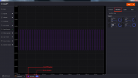
Test phase configuration 3. Set signal generator channels 1 and 2 to either Sine or Triangle waveform type, they should be the same. For channel 1 set Amplitude: 5V, Frequency: 5kHz, offset: 0V and phase: 0°. Set signal generator’s channel 2 to Amplitude: 5V, Frequency: 5kHz, offset: 0V and phase: 180°. Set Oscilloscope’s both channel to Time Base: 200us, Volts/Div: 1V The interface should look like in the “Step Resources” picture (left side)
4. Run Oscilloscope, add channel with an input function: f(t) = sin(t1) + sin(t0). The new plot’s value should be very close to 0V ranging around -0.2V to 0.2V
5. Set signal generator channels 1 and 2 to either Sine or Triangle waveform type, they should be the same. For channel 1 set Amplitude: 5V, Frequency: 5kHz, offset: 0V and phase: 0°. Set signal generator’s channel 2 to Amplitude: 5V, Frequency: 5kHz, offset: 0V and phase: 360°. Set Oscilloscope’s both channel to Time Base: 200us, Volts/Div: 1V The interface should look like in the “Step Resources” picture (left side)
6. Run Oscilloscope, add channel with an input function: f(t) = sin(t1) - sin(t0). The new plot’s value should be very close to 0V ranging around -0.2V to 0.2V

Test Results will be recorded in the following document: Signal Generator Test Case


Return to Test Cases Table of Contents

university/tools/m2k/scopy/test-cases/signal-generator.1501471046.txt.gz · Last modified: 31 Jul 2017 05:17 by Dann Kristofer Bautista