This section provides the brief overview of creating a SigmaStudio+ project.
Following are the steps required to create a new SigmaStudio+ schematic:
Step 1: Create a New Project File
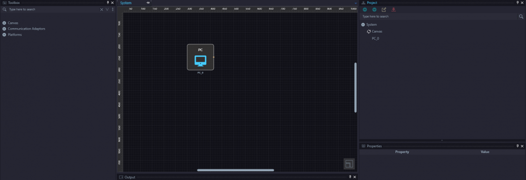
Launch SigmaStudio+. Select “File → New Project” from the application's main menu or click the “New Project” button on the application toolbar to create a new project. New projects are created with the default project name ‘Project’ and the ‘System’ tab will be displayed. New projects are created with PC block (non-removable).


Step 2: Connect the Communication Interface
Drag and drop the communication interface to the system window and connect to PC block.

Different types of connections
1. USB connection where in user connects PC with the communication device

2. SPI connection where in user connects the communication device with the desired platform selected

3. I2C connection where in user connects the communication device with the desired platform selected

4. A2B connection where in user connects the A2B main node with the sub node

5. Normal connection between the algorithms

Rules for making a connection
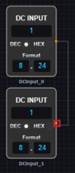
* The connection should be between target and source pin and vice versa. A connection between target and target or source and source is not valid (Note: The red box around the end point of the connection in the image below denotes the connection is not valid).

* The target and the source pin type should be same in order to create a connection. For example, source SPI pin cannot be connected to target I2C pin.

Step 3: Choose one of the default Platforms or build a Custom Platform
Before beginning schematic design, at least one platform block should be connected. Drag and drop platform block onto the system window from “Toolbox's - Platforms” category. The available algorithm blocks differ for each DSP platform, so it is important to select the DSP platform that you intend to use for your schematic design.
The Analog Device EZ Kit platforms can be directly used by drag and drop platform block onto the system window.

For custom platform, drag and drop custom platform block onto the system window.

Double click on the custom platform block, drag and drop required Single or Dual SHARC core processor block onto the platform window.

Please select the appropriate dual SHARC+ core processor for the custom platform from the list of processors under “Project Window » CustomPlatform_x » ADSPSC5xx_x » Settings”.

Please select the appropriate Single SHARC+ core processor for the custom platform from the list of processors under “Project Window » CustomPlatform_x » ADSP2156x_x » Settings”.

Note that, it's possible to create designs with more than one processor based on custom platform.
Connect the custom platform to the communication interface.

For more information about supported platforms and processors, please refer to.
Supported Platforms & Processors
Step 4: Add Algorithm blocks to the Schematic
Double click on the processor block of the platform to go to schematic design window.

Please note, for multi core processors, core will be displayed first. The schematic design window will be opened by double clicking on the core block

The schematic window will contain input and output block by default. The algorithm blocks for the corresponding DSP processor available in “Toolbox” on the left side of schematic window. The algorithm blocks can be dragged and dropped to schematic window to design the audio signal flow.
Note: Every schematic should contain either an input block or a source block. If no inputs are present in the schematic design, you will receive the compiler error: Error - No Inputs are defined for IC.
Step 5: Create a Signal Processing Design
Algorithm/Function blocks are managed in the Schematic tab.
Drag and drop blocks from the Toolbox pane into the schematic tab to create your design. Note that in additional to advanced signal processing blocks, there are a variety or low-level building blocks available (delay, multiply, and addition, feedback) allowing you to implement custom algorithms to fulfill your specific design requirements.
Step 6: Outputs
To output processed signals from the DSP hardware, you will need to insert an Output block into the schematic design. Drag and drop output blocks from the Toolbox pane into the schematic tab. The output blocks represent the hardware's physical analog and digital output pins.
Step 7: Connect Inputs to Outputs
Each schematic block has input and output pins which can be wired together to create the system's signal flow. All input pins must be connected to a source or another block's output pin.
Note: If there are unconnected pins in the schematic you will receive the compiler error: Unconnected input pins found in <moduleID/Label>.
Step 8: Link and Compile the Project
Once the schematic is complete and all blocks are correctly wired together, you can link and compile the project. If any errors are encountered during compilation, the error information will be displayed on the Output Window. If compilation is successful, application's status will change to 'ACTIVE' on the bottom right corner. Please refer to Link and Compile Options for different Link and compiles options.
Note: The designed schematic can be “Link Compile” or “ Link Compile download” straight away when you are using SigmaDSP processors. In case of SHARC processors there are additional settings to be done for successful compilation.
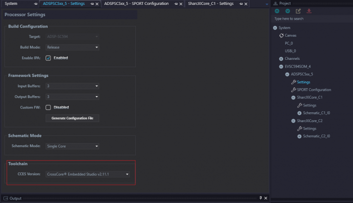
* PC should have CrossCore Embedded Studio (CCES) with a valid license for SHARC processors. Please check the CCES version selected for compilation in processor settings.

* Review the SPORT settings for the target application based on your platform design

* Select corresponding application executables (DXE's) for each of the cores in SHARC Core settings window

* The target application should be run before “Link Compile Download” operation. Please refer to Getting Started for more details on hardware setup and how to execute the example.
Step 9: Adjust Controls in Real-time
Once your schematic is compiled and downloaded to the hardware, you can adjust the schematic's controls (knobs, sliders, and spin boxes) to change algorithm parameters in real time. This allows you to tune your design's settings before implementing the final system. See System Implementation for more information about how to integrate a schematic design into your end system.