


This version is outdated by a newer approved version. This version (01 Sep 2017 15:27) is a draft.
Approvals: 0/1
This version (01 Sep 2017 15:27) is a draft.Approvals: 0/1
This is an old revision of the document!
Table of Contents
Click here to return to the Dynamics Processors page
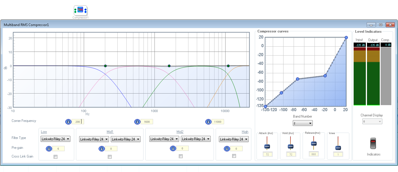
RMS 4 Band Compressor(ADAU145x)

RMS 4 band compressor is a multi-band compressor with 4 unique filter bands each with a unique compression curve and setting. The filter bands are configurable allowing the user to adjust the frequencies fed to each compression curve. Each compressor curve is individually configurable by means of a Graph and settings - attack, release hold and knee. The compression is applied by detecting the RMS value of the input signal and multiplying it with corresponding gain as set in the graph.
Input Pins
| Name | Format [int/dec/float] - [control/audio] | Function Description |
|---|---|---|
| Pin 0: Input Signal | decimal(ADAU145x)- audio\\ | Input signal to be compressed |
Output Pins
| Name | Format [int/dec/float] - [control/audio] | Function Description |
|---|---|---|
| Pin 0: Compressor Out | decimal(ADAU145x)- audio- audio | The compressor output |
Grow Algorithm
The module supports growth functionality. Add is not supported.
GUI Controls
| GUI Control Name | Default Value | Range | Function Description |
|---|---|---|---|
| corner frequency low | 40Hz | 10-10000Hz | cross over frequency at the intersection of the lowpass band and midband1 |
| corner frequency mid | 600Hz | 10-10000Hz | cross over frequency at the intersection of the midbands |
| corner frequency high | 8000Hz | 10-10000Hz | cross over frequency at the intersection of the highpass band and midband2 |
| Filter Type | 0(linkwitz riley 24) | 0-10 | filter type (linkwitz, butterworth, Bessel) |
| Link channels | disabled | enable/disable | links cross channel rms gains |
| attack | 72 ms | 1- 500 (ms) | attack time, time in which compression kicks in when the input crosses the threshold |
| hold | 72 ms | 1- 500 (ms) | hold time |
| release | 868 ms | 1- 2000 (ms) | release time, time in which the compression is deactivated when the input falls below the threshold |
| knee | 1 | 1-75 | softness of the compression kicking in determined by the knee |
| indicator | disable | enable/disable | enables or disable the gain display meters |
| compression curve | - | - | enables the user to define the compression curve by moving the points on the curve along the graph |
DSP Parameter Information
| GUI Control Name | Compiler Name | Function Description |
|---|---|---|
| NumFilt | FirFiltPoolS300Alg1Numfilt(ADAU145x) FirFiltPoolBlkAlg1Numfilt(214xx) | The Number of filter coefficient sets |
| TapSize | FirFiltPoolS300Alg1TapSize(ADAU145x) FirFiltPoolBlkAlg1TapSize(214xx) | The Number of filter taps in each coefficient set |
| InIndx | FirFiltPoolS300Alg1InIndx(ADAU145x) FirFiltPoolBlkAlg1InIndx(214xx) | The selected input index |
| FiltIndx | FirFiltPoolS300Alg1FIltIndx(ADAU145x) FirFiltPoolBlkAlg1FiltIndx(214xx) | The Selected filter coefficient set index |
| RevIndx | FirFiltPoolS300Alg1RevIndx(ADAU145x) FirFiltPoolBlkAlg1RevIndx(214xx) | The Selected Reverse Index, if set(value=1), the coefficient access order for filtering is reversed |
| InvIndx | FirFiltPoolS300Alg1InvIndx(ADAU145x) FirFiltPoolBlkAlg1InvIndx(214xx) | The Selected Invert Index, if set(value=1), the output value is negated |
Algorithm Description
The Algorithm implements a FIR filter of order N, having N+1 filter taps. Multiple coefficient sets can be added to the module, enabling the routing of multiple inputs through multiple independent FIR filters to a given output selection line.
The FIR Filter Pool form has multiple tabs each having a particular routing selection and parameters between the inputs and outputs. The algorithm implements invert functionality which inverts the output samples and Reverse which access the loaded filter coefficient set in reverse for a particular selection.

Example
The example shows The module configured to two inputs and three output channels with three independent FIR Filter coefficient sets. The three coefficients are Low pass FIR filters with cutoffs 2.4KHz,4.8kHz and 7.2KHz.
The output plots for the configuration are shown below.


Supported IC's
1. ADAU145x
2. 214XX
3. 213xx
4. SC58x
resources/tools-software/sigmastudio/toolbox/dynamicsprocessors/rms4band.1504272463.txt.gz · Last modified: 01 Sep 2017 15:27 by Prasad Kamath