 This version (21 Jun 2012 20:41) was approved by William Jahn.
This is an old revision of the document!
Click here to return to the Basic DSP page
| Name | Format [int/dec] - [control/audio] | Function Description |
|---|---|---|
| Pin 0: Input | integer or decimal - control or audio | Input signal that will be mapped via the linear interpolation function |
| Name | Format [int/dec] - [control/audio] | Function Description |
|---|---|---|
| Pin 0: Output | integer or decimal - control or audio | Output signal which is the result of the linear interpolation function |
| GUI Control Name | Default Value | Range | Function Description |
|---|---|---|---|
| Max | 5 | -15.99 to +15.99 | The maximum allowable input value. For full-scale audio, use 1. |
| Min | 1 | -15.99 to +15.99 | The minimum allowable input value. For full-scale audio, use -1. |
| Pts | 5 | 1 to 100 | The number of points in the linear interpolation function |
| Table | [1, 2, 3, 4, 5] | -16 to 15.9999999 | The points in the linear interpolation function. The input signal will be mapped to this data set. |
| GUI Name | Compiler Name | Function Description |
|---|---|---|
| Table | LinearIntAlg1_1 | First point in the index table |
| Table | LinearIntAlg1_p1_1 | Second point in the index table |
| Table | LinearIntAlg1_p1_1_autoincremented … | Third and greater points in the index table |
| Min | LinearIntAlg1Min_2 | Minimum input value |
| Max | LinearIntAlg1Q_2 | Difference between the minimum input and the maximum input |
| Pts | LinearIntAlg1Number_2 | Number of points in the index table minus 1. For example, if there are 3 points in the table, this parameter will be 2. |
The linear interpolation cell performs interpolation of a data set.
The input of the linear interpolation cell must lie between a set minimum and maximum value. The input values between the min and max input values are mapped linearly to an index number between 0 and n, with n representing the maximum index.
For example, if input = min, then index 0 is selected. If input = max, then index n is selected. If the input lies halfway between two indices, then the output will be the average of the two corresponding points in the data set.
The process of mapping an input to an index is shown graphically below:

The actual output of the cell depends on the values of the data set stored in the index table. The example below shows a table with 6 points. If index = min, then the output will be the value of the point stored in index 0. If index = 5, then the output will be the value of the point stored in index 5. If, for example, the input is one third of the way between indices 2 and 3, then the output will be (index_2 * 2/3) + (index_3 * 1/3). This is illustrated by the orange point in the graphic below - the cell's output would be the value of the orange point's displacement on the vertical axis. The blue points represent values stored in the index table. The lines connecting the blue points represent the “interpolants.” The output value of the cell will always lie on an interpolant.

If the input is below the defined minimum or above the defined maximum, the output of the cell will be unpredictable. Care should be taken to limit the input signal accordingly.
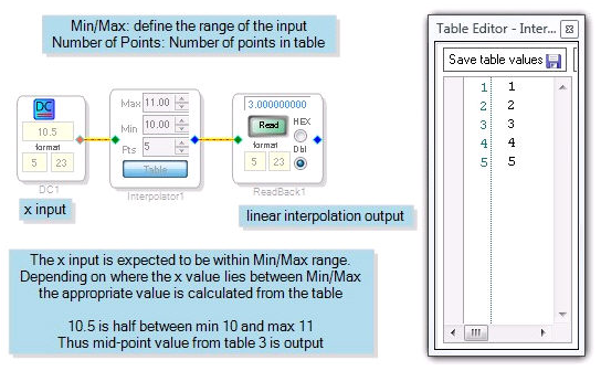
The example below shows a linear interpolator cell that is set up to interpolate for inputs between 10 and 11. The input, supplied by a DC Input cell, is 10.5. Since 10.5 is exactly the midpoint between 10 and 11, the midpoint of the table, 3, is output. A DSP Readback cell is used to confirm the output of the Linear Interpolator cell.

| Toolbox Path | Basic DSP - Index LUT - Linear Interpolator |
| Cores Supported | ADAU1761 ADAU1781 ADAU144x ADAU170x AD1940 |
| “Grow Algorithm” Supported | no |
| “Add Algorithm” Supported | no |
| Subroutine/Loop Based | no |
| Program RAM | 18 |
| Data RAM | 6 |
| Parameter RAM | 5* |
*Based on an index table with two points. As points are added, Parameter RAM usage will increase by 1 per index.