Click here to return to the Basic DSP page
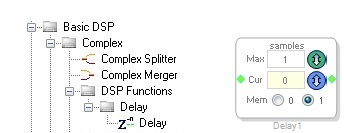
The Delay block outputs a delayed version of the input signal. The input is delayed by the amount of samples reflected in the Cur numeric text box. The top drop-down menu labeled Max represents the largest amount of delay that could be applied to the input signal. If you select a new Max value in the drop-down menu, you will be forced to recompile.
The maximum delay available for a particular delay block depends on the total available system data RAM, which is specified in the DSP processor data sheet. Setting the Max control's value, allocates memory on the DSP, reserving that memory for use by this particular block only, and reducing the available memory for all other delay blocks in the design. This is a compiler directive and modifies the assembly code, so any time you change the Max setting you must recompile and download the program. The maximum delay value range is limited to the remaining unallocated memory of the RAM.
There are two version of ' Delay ' algorithm.
Delay the input samples in time domain by the amount of Current delay. The size of the delay buffer is Max delay.

Delay the input samples in frequency domain by the amount of current delay. This is a block based module. The size of the delay buffer is Max delay * 2 + BlockSize *2.

| Name | Format [int/dec] - [control/audio] | Function Description | |
|---|---|---|---|
| Pin 0: Complex Input | complex | audio | Input complex signal |
| Name | Format [int/dec] - [control/audio] | Function Description | |
|---|---|---|---|
| Pin 0: Complex Delayed Output | complex | audio | Complex Output signal |
| GUI Control Name | Default Value | Range | Function Description |
|---|---|---|---|
| Max | 1 | 1 - (Depends on Size of the Memory available) | This control specifies the maximum delay supported for the current instance in samples (32-bit word). Change in this value requires a re-compilation |
| Cur | 0 | 1 - Max | Current delay value |
input pins and output pins can be grown up to 16 channels together. Add algorithm and Multiple instance of the module is supported.
| GUI Control Name | Compiler Name | Function Description |
|---|---|---|
| Cur | ComplexDelayBlkAlg1delay | Current Delay value in bytes. (Cur * 4) |
Here,
ADAU145x