


This version (23 Aug 2022 15:44) was approved by valerie hamilton.The Previously approved version (19 Jul 2022 16:24) is available.
AD74115H EFT Test Results
The electrical fast transient (EFT) immunity test indicates the capability of the device to maintain data integrity during repetitive electrical fast transients and bursts, which often occur from arcing contacts in switches and relays.
Table 1 IEC 61000-4-4 Test Levels Signal and Control Ports
| Level | Voltage Peak (kV) | Repetition Frequency(kHz) |
|---|---|---|
| 1 | 0.25 | 5 or 100 |
| 2 | 0.5 | 5 or 100 |
| 3 | 1 | 5 or 100 |
| 4 | 2 | 5 or 100 |
Per the IEC 61000-4-4 standard, the DUT (Device under test) is tested with 2000 V discharges on the analog input cable. Positive and negative polarity discharges are applied. The duration time of each test is 1 min. The transient and burst waveform is in accordance with IEC 61000-4-4, 5 ns rising time with 50 ns pulse width. 5 kHz repetition frequency was used for the test.
The configuration consists of a 0.8 m high wooden table, covered with a sheet of copper that is at least 0.25 mm thick, and connected to the protective grounding system. The DUT is placed on a 0.1 m thick isolating support. A minimum distance of 0.5 m is provided between the DUT and the walls of the laboratory.
Hardware Configuration
Due to the configurability of the AD74115H some use cases were covered other use cases by default reducing the amount of testing required. Some use cases used a different measurement path to cover another use case. The list below shows the coverage:
- Current Output Use Case covers:
- Voltage Input use case since the measurement path is identical (SENSELF to AGND_SENSE).
- Current Output (RSENSE) Use Case covers:
- Current Input Loop Powered use case by using a different ADC configuration (measure across RSENSE --> SENSEHF to SENSELF).
- Current Input Externally Powered use case by the current input loop powered use case since the measurement path is the same (SENSEHF to SENSELF).
- Voltage Output use case as the output paths are the same and the measurement path is covered by current input loop powered.
- Shielded cable was connected to IO_P and IO_N and a 500 Ω load while the output was set to 12.5 mA.
- DMM used to measure the output at the load for current output use case.
- Internal ADC was used to measure current across RSENSE for current output RSENSE use case.
- 4 Wire RTD Use Case covers:
- 2 and 3 wire RTD use case as the output path is the same for all. The measurement path is covered by the addition of SENSE_EXT1 and SENSE_EXT2.
- Shielded cable was connected to the screw terminals to a junction box and a RTD connected at the junction box.
- Internal ADC used to measure the RTD resistance.
- Digital Input Logic Use Case covers:
- Digital Input Loop Powered use case as the measurement path is the same. The loop powered is covered by the current output use case.
- Unshielded cable was used.
- A voltage source was used to source 8 V to IO_P via a 1 k resistor. The voltage was swept from 8 V to 10 V for a random number of times to ensure the digital counter was counting each voltage transition correctly.
- The counter was checked before and after the testing.
- Digital Output use case in the off condition. The digital output circuitry is physically connected at the output path. If the digital output switched on unexpectedly it would be detected.
- Digital output internal use case used a 390 Ω load and the voltage was measured at the load with the DMM. The current was then calculated using ohms law.
- Digital output external use case used a 250 Ω load and measured the same as digital output internal.
There was a digital multi meter (DMM) connected to the output load to ensure there was no loss of output during testing and also to ensure the integrity of the internal ADC measurement. To protect the DMM a low pass filter was placed between the load and DMM. The measurements were streamed back to the laptop throughout the testing.

Figure 1 ADP1034 and AD74115H EFT Current Use Case Setup
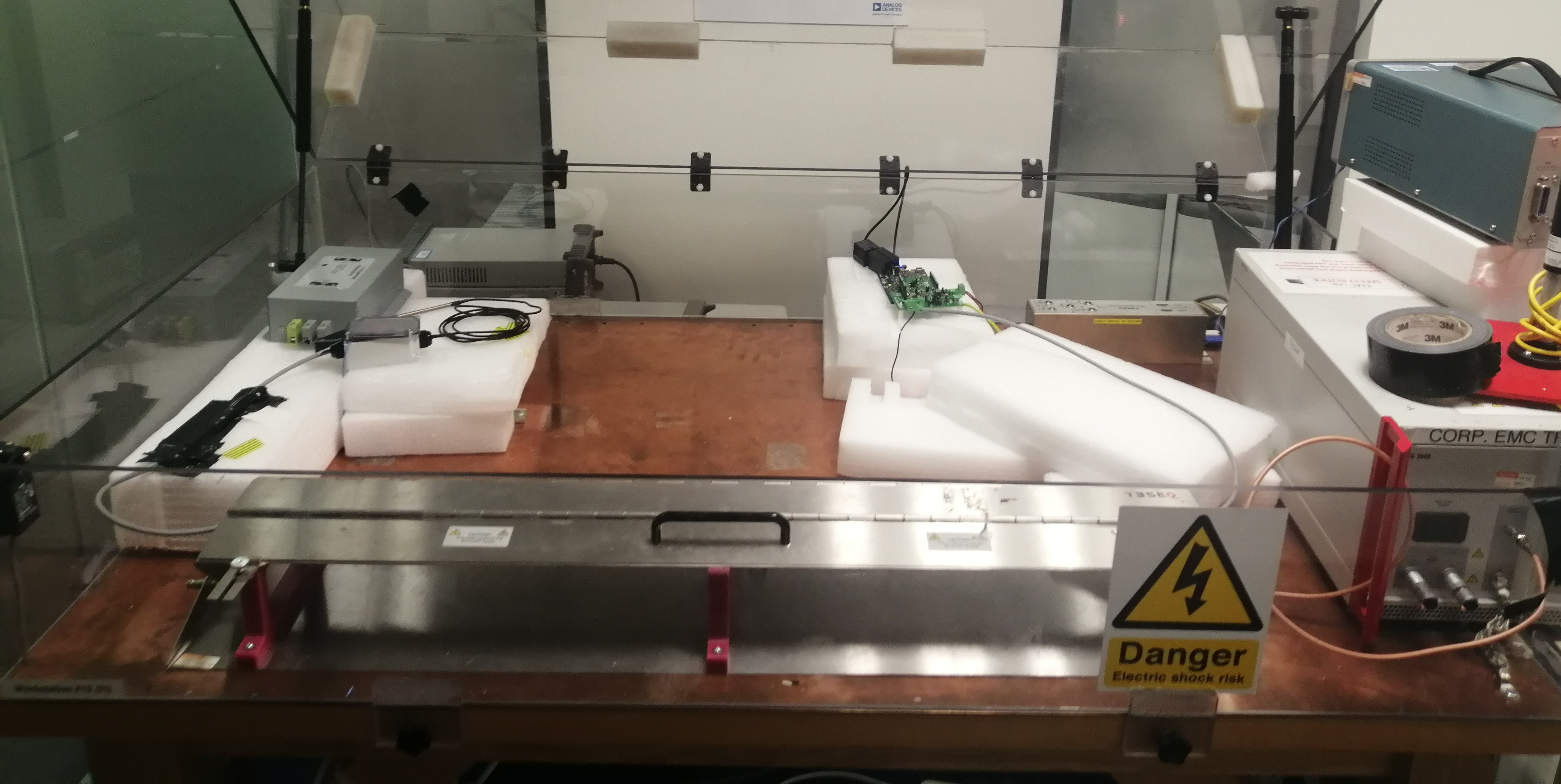
Figure 2 ADP1034 and AD74115H 4 wire RTD EFT Setup

Figure 3 ADP1034 and AD74115H Current Output Test Setup

Figure 4 ADP1034 and AD74115H Digital Input Logic Test Setup
Software Configuration
The software was written in python to facilitate interaction with DMM and DUT simultaneously. At the beginning of each test the pre test configuration was performed. Before the discharges were applied the pre measurement flow of 1000 samples were taken. After discharges the post measurement of 1000 samples were taken. Each sample (ADC and DMM) was taken approximately every 25 ms. Pre test configuration
- Reset DUT
- Clear alert status register
- Configure channel use case
- Configure ADC measurement nodes
- Configure ADC sample rate for 20 SPS
Pre and Post Measurement Flow
- Read and store alert status register
- Clear alert status register
- Read ADC code
- Read DMM measurement
- Save data to file
- Repeat 1000 times
Performance Summary
Table 2 gives a summary of the EFT test results. The AD74115H was tested to level 4 according to IEC 61000-4-4 and achieved class B. There were no alert status bits activated throughout the testing. For the digital output use cases a deviation is not recorded as the accuracy is dependent on the load. The test verified that the digital output did not turn off unexpectedly.
Table 2 EFT Results
| Test Level | Use Case | Measurement Method | Pre Test Average | Post Test Average | Deviation (%FSR) | Performance |
|---|---|---|---|---|---|---|
| 2 kV | Current Output | DMM | 12.47058 mA | 12.47095 mA | - 0.00112 | Class B |
| Current Output RSENSE | ADC | 12.48626 mA | 12.48615 mA | - 0.000438 | Class B | |
| 4 Wire RTD | ADC | 108.60329 Ω | 108.58727 Ω | - 0.00305 | Class B | |
| Digital Input Logic | Internal Counter | 6 | 6 | 0 | Class B | |
| Digital Output Internal | DMM | 57.49649 mA | 57.50053 mA | N/A | Class B | |
| Digital Output External | DMM | 80.8106 mA | 80.65714 mA | N/A | Class B | |
| - 2 kV | Current Output | DMM | 12.49751 mA | 12.49579 mA | - 0.00688 | Class B |
| Current Output RSENSE | ADC | 12.48614 mA | 12.48626 mA | 0.00046 | Class B | |
| 4 Wire RTD | ADC | 108.59528 Ω | 108.59528 Ω | 0.00000 | Class B | |
| Digital Input Logic | Internal Counter | 7 | 7 | 0 | Class B | |
| Digital Output Internal | DMM | 57.49162 mA | 57.50294 mA | N/A | Class B | |
| Digital Output External | DMM | 80.66309 mA | 80.66651 mA | N/A | Class B |
resources/technical-guides/eft.txt · Last modified: 23 Aug 2022 15:44 by valerie hamilton