This version (07 Nov 2012 14:52) was approved by Andrei Cozma.
This is an old revision of the document!
Hardware Setup
Before connecting the
ADI evaluation board to the Xilinx KC705 make sure that the VADJ_FPGA voltage of the KC705 is set to 3.3V. For more details on how to change the setting for VADJ_FPGA visit the Xilinx KC705 product page.

At this point everything is set up and it is possible to start the evaluation of the ADI hardware through the controls in the uC-Probe application provided in the reference design.
Launch uC-Probe from the Start → All Programs → Micrium → uC-Probe.
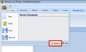
Select uC-Probe options.

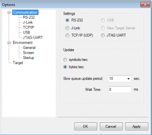
Set target board communication protocol as RS-232

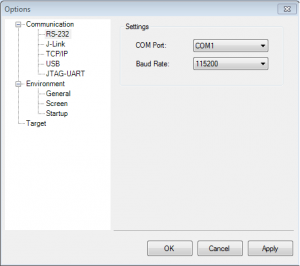
Setup RS-232 communication settings
Select the RS-232 option from the Communication tab.
Select the COM port to which the KC705 board is connected.
Set the Baud Rate to 115200 bps.

Load and Run the Demonstration Project

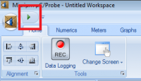
In some cases it is possible that the uC-Probe interface will not respond to the commands the first time it is ran. In this situation just stop the interface by pressing the Stop button and run it again by pressing the Play button.
After starting the uC-Probe interface wait until the status of the connection with the board displayed on the bottom of the screen is set to Connected. It is possible to use the interface only after the status is changed to Connected and the data transfer speed displayed next to the connection status is different than 0.