


This version (01 Mar 2019 17:12) was approved by Micheál Lambe.
Table of Contents
AD5940_SqrWveVoltammetry
This example will use EVAL-ADICUP3029 and EVAL_AD5940ELCZ to carry out a square wave voltammetry measurement. Note, the corresponding application example in the SDK is the AD5940_SqrWveVoltammetry project.
Overview
Square wave voltammetry is an electrochemical technique where the voltage between the reference and sense electrode is incremented in a square wave fashion as in figure below. The response current on the working electrode is measured after each half step.

For more details refer to the application note, AN-1563.
Measurement Requirements
The following is a list of items required to carry out the measurement.
- Hardware
- EVAL-ADICUP3029
- EVAL-AD5940ELCZ
- Mirco USB to USB cable
- PC or Laptop with a USB port
- Custom Cables (Optional)
- Software
- AD5940_SqrWveVoltammetry Example Project (Git Lab)
- Serial Terminal Program, Such as Putty or RealTerm
- IDE such as IAR or Keil
Setting up the Hardware
- Set switch S2 to USB Arduino function in order to view data over UART. The UART baud rate is 230400
- Set S5 to Wall/USB to power the board from the USB cable
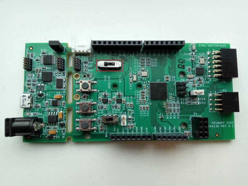
- Place the EVAL-AD5940ELCZ on top of the EVAL-ADICUP3029.
- Ensure jumper on JP10 and JP11 is on PIN2 and PIN4
- Place jumper in position B on JP6 to connect the 1kΩ||3kΩ RE0 and SE0
- Plug in the micro USB cable into the (P10) USB port on the EVAL-ADICUP3029, and the other end into the PC or laptop.


Obtaining the Source Code
The source code and include files for the project can be found on Git
The source code and include files of the AD5940_SqrWveVoltammetry can be found in the SDK below:
Configuring the Software
To compile and run the example open the project in either Keil or IAR. The AD5940RampStructInit() function is used to configure the main application parameters that control the excitation signal and the data acquisition. The parameters and their description are explained in the table below:
| Variable Name in Firmware . | Name on diagram | Description |
|---|---|---|
| RampStartVolt | E1 | This variable sets the voltage at which the excitation signal begins |
| RampPeakVolt | E2 | This sets the peak voltage of the signal. T |
| VzeroStart | This sets the start voltage of Vzero. Optimully set to 1.3V. The Actual start voltage on the sensor pin is VzeroStart + RampStartVolt | |
| VzeroPeak | This sets the peak voltage of Vzero. Optimully set to 1.3V. The Actual peak voltage on the sensor pin is VzeroPeak + RampPeakVolt | |
| Frequency | Frequency | This sets the frequency of the square wave signal |
| SqrWvAmplitude | Ep | This sets the amplitude of the square wave signal |
| SqrWvIncrement | Estep | This sets the increment voltage step after each square wave |
| SampleDelay | t | This variable sets the duration from when the step is applied to when the ADC measures the response current. Note, the SampleDelay must be shorter than the total step width. There are no checks in firmware. |

Outputting Data
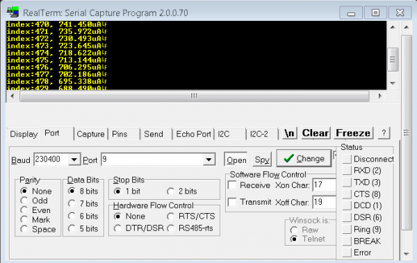
The measurement results are sent to the PC via UART. To establish connection over UART, connect the Micro-USB cable to the PC and to the EVAL-ADICUP3029 board. A terminal program such as RealTerm or Putty is required to display the results
Following is the UART configuration.
  Select COM Port
  Baud rate: 230400
  Data: 8 bit
  Parity: none
  Stop: 1 bit
  Flow Control: none
The data on the terminal indicates the index number of the data point and the current measured in µA.
resources/eval/user-guides/eval-ad5940/software_examples/ad5940_swv.txt · Last modified: 19 Nov 2018 10:54 by Micheál Lambe