


This version is outdated by a newer approved version. This version (11 Sep 2018 09:41) was approved by Gowtham shanmugaraj, Jeric Vargas.The Previously approved version (11 Sep 2018 09:40) is available.
This version (11 Sep 2018 09:41) was approved by Gowtham shanmugaraj, Jeric Vargas.The Previously approved version (11 Sep 2018 09:40) is available.This is an old revision of the document!
Table of Contents
Power Measurement on COG Platform
The power measurement procedure is same for EV-COG-AD3029LZ, EV-COG-AD4050LZ, EV-COG-AD4050WZ and EV-COG-AD4050WZ.
The MCU Cog boards EV-COG-AD3029LZ and EV-COG-AD4050LZ and EV-COG-AD4050WZ offer flexibility in terms of power supply and power isolation options for the circuits present on board.It allows the user to power optimize the board for a specific application by isolating or disconnecting some of the circuits which are not used otherwise. True MCU current and EEMBC ulpbench score can be reproduced with proper circuit isolation on the MCU cog board and multiple test points are provided for monitoring current consumption at various points. This wiki page describes the procedure to measure current consumption of the cog boards and to power optimize various applications.
Current measurement test points on COG
| Current Test point | Description | Purpose | How to do current measurement |
|---|---|---|---|
| TH1 | Current test point between external supply VIN and regulator | To supply/measure the overall board current | Connect an ammeter across the test point |
| TH2 | Current test point between cog board supply (VDD_MAIN) and VDD_MCU | To supply/measure the current consumed by the MCU alone | Connect an ammeter across the test point |
| TH3 | Supply test point | To monitor VDD_MAIN | |
| TH4 | Current test point between cog board supply (VDD_MAIN) and VDD_RF | To supply/measure the current consumed by the RF module alone | Connect an ammeter across the test point |
| TH5 | Current test point between MCU's GPIO and VDD_MCU_B | Supplies the I2C pullups present on board | If needed, connect an ammeter across the test point |
Removing the jumper on these test points except TH3 cut downs the supply to the respective block, unless an ammeter is connected across these test point during current measurement
Power isolation jumpers
The following figure shows jumpers which connect the on board components to the VDD_MAIN supply rail.
 To do current profiling for any application, connect the ammeter as shown in overall board current measurement and remove some of the following jumpers if applicable.
| Jumper | Action | Description |
|---|---|---|
| JH5 | Remove | powers up MBED. If UART is not used to print the messages in the application after downloading the firmware, disconnecting the MBED circuit would save ~10-12mA. |
| JH6 (top side) | Remove | Connects reset from MBED to MCU's reset circuit. If not removed while isolating MBED circuit, leakage current of ~1uA is expected |
| P8 (top side) | Remove | If MCU UART lines are connected to RF UART lines or External UART lines, this is not required. If not, while disconnecting the MBED remove the jumpers on this header to avoid leakage through UART lines |
| JH3 | Remove | If debug LEDs are not used, disconnecting these LEDS would save ~2mA |
| JH7 | Remove | Disconnects ADXL362 from VDD_MAIN (do only if necessary) |
| JH8 | Remove | Disconnects ADT7420 from VDD_MAIN (do only if necessary) |
Measuring overall board current
This section briefs about the jumper settings and wire connections to measure the overall board current. The default jumper settings on the COG board before the measurement is shown in the following figure.
 The following figure shows the connection to measure the overall board current. Remove the jumper on TH1 and connect an ammeter across the test points.

Measuring MCU current
Measuring MCU active mode current
To measure the MCU current, remove the jumper present on TH2 and connect an ammeter across TH2 as shown in the following figure (left). Other jumper can be left in default position. The measured MCU (ADuCM3029) active current is shown in the figure on the left.

Measuring MCU sleep mode current
To measure proper MCU sleep current, it is recommended to isolate some of the on board circuits such as debug LEDs and MBED (refer to power isolation jumpers section).
- Remove JH5 and JH6 to disconnect MBED
- Remove JH3 to disconnect Debug LEDs
The following figure shows the front and back side of the board with the above mentioned jumpers removed and an ammeter is connected across TH3 to measure MCU sleep current.
 The overall MCU sleep current measurement setup is shown in the following figure. The measurement for MCU sleep mode is shown as an example. Note that the reading shown in the figure is an averaged value.
 By default, the board supply is fed from the on board step down regulator ADP5300 operating in Hysteresis mode. If the measured sleep current readings are not averaged, then observing spikes in the current profile at regular intervals is expected as shown in the following figure.
 This is because, the regulator switches between active and standby mode to save power. When the output voltage is just above the upper hysteresis threshold voltage, the regulator enters standby mode by disabling majority of the circuitry. The regulator then wakes up and charges the load capacitor when the output voltage decreases below the lower hysteresis threshold. Due to this switching, current spikes are expected to be seen in the output.The frequency of switching is not fixed in hysteresis mode and it depends on the load. As the load increases, the switching frequency also increases. But in PWM mode, the regulator always operates at a switching frequency of 2 MHz.
Bypassing the regulator and powering COG with a coincell
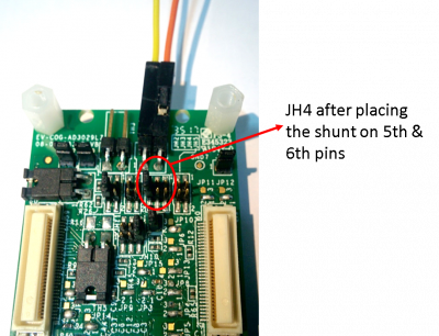
In case of powering the COG board by using a CR2032 3V coin cell with minimal circuits, the on board regulator can be bypassed. Bypassing the regulator allows the 3V coin cell to directly supply the board. By do so, the ripples seen in the regulated output can be avoided and MCU current without any spikes can be observed. The following figure shows the jumper configuration for JH4 to bypass ADP5300. Insert the shunt on 5 & 6 positions of JH4.
In the figure, MBED circuit and debug LEDs were also disconnected to reduce the load on 3V coincell. Otherwise the output voltage from the coin cell would drop considerably
 The power switch position and overall jumper configurations are shown in the following figure. To monitor the battery voltage, a voltmeter is connected across TH3 (refer to Current measurement test points section).
 The overall current measurement setup measuring MCU hibernate current with full SRAM retention is shown below.

Bypassing the regulator and powering COG with an external power supply on VDD_MAIN
The COG boards can be powered up by an external power supply other than the USB and coin cell. The external supply can be connected to VDD_MAIN directly bypassing ADP5300.
external supply must be below 3.6V, if it is directly connected to VDD_MAIN
The shunt on JH4 must be removed to directly connect the source meter to VDD_MAIN as shown below. Other jumpers can be left in default position.

The source meter must be connected to TH3.
- connect positive lead to pin 1 of TH3
- connect negative lead to pin 2 of TH3
The following figure shows the overall current measurement setup. In addition to source meter, an ammeter is connected across TH2 to measure MCU current.

Powering the COG from an external supply (VDD_MAIN) through EV-GEAR-EXPANDER1Z
One of the power up options for COG is through an external supply on VDD_MAIN rail. To power up COG from an external source,
- change the switch position to 1 in S7 (this avoids the conflict in the power supply in case USB is connected).
- Insert the shunt in 3 & 4 positions on JH4 as shown in the following figure. Other jumpers can be default positions.

- Connect the MCU COG board to EV-GEAR-EXPANDER1Z board via C1 & C2 connectors
- Connect the power supply to EV-GEAR-EXPANDER1Z as shown in the following figure

The voltage source must be between 1.8V and 3.6V. In this setup, the VDD_MAIN rail is directly sourced from an external power source bypassing the on board regulator. Connecting a source with voltage level more than 3.6V would damage the on board components.
End of Document
resources/eval/user-guides/ev-cog-ad3029lz/powermeasurement.1536651693.txt.gz · Last modified: 11 Sep 2018 09:41 by Gowtham shanmugaraj