The EVAL-CN0551-EBZ is a four-layer printed circuit board (PCB) that allows evaluation of the CN0551 USB-powered, 433.92 MHz RF power amplifier circuit. The board is fabricated with a 2 oz./2 oz. copper cladding and IPC-4101 (or IPC-4103) laminates and bonding materials.
Designed to be used with the ADALM-PLUTO, the EVAL-CN0551-EBZ features a small form-factor with dimensions of 25.40 mm × 60.25 mm x 1.57 mm (PCB only). The evaluation board uses standard 50 Ω SMA coaxial connectors for its RF signal path — for easy integration with RF systems; a male connector is used for the RF input and a female connector is used for the RF output. Coplanar waveguides are used for the RF traces on the board, which have a characteristic impedance of 50 Ω. A micro-USB connector is used for the input power, allowing the evaluation board to use most +5 V wall-wart power supplies available in the market.
Evaluation Kit Contents:
 The RF input to the evaluation board must be connected to the male SMA connector J1.
The maximum RF input to the EVAL-CN0551-EBZ is -3 dBm. Do not use a higher input level to avoid damaging the circuit.
 The RF output of the evaluation board must be connected to the female SMA connector J2.
The maximum RF output of the EVAL-CN0551-EBZ is +27 dBm. Ensure that the RF load to be driven can handle the amplified RF signal. Use an RF attenuator if necessary to avoid damage.
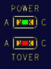
The evaluation board uses two LEDs to indicate its current status.
 The green LED (POWER) lights up when power is present on the board, the red LED (TOVER) lights up when the amplifier circuit is disabled due to the board temperature exceeding the temperature switch trip point.
| LED Indications of Board Status | ||
|---|---|---|
| POWER | TOVER | Board Status |
| Off | Off | No power |
| On | Off | Normal operation |
| On | On | Overtemperature (ADL5324 is disabled) |
 A +5 V power supply must be connected to the VCC line through the micro-USB port P1.
The total typical supply current of the on-board RF amplifiers is 175 mA. However, this requirement increases at higher temperatures (refer to Page 11, Figure 26 on the ADL5324 data sheet and Page 12, Figure 34 on the AD8353 data sheet for more information). As such, it is recommended to use a power supply with a maximum current rating of at least 0.5 A to ensure full functionality.
The trip point of the temperature switch can be set using the solder jumpers JP1 and JP2, as shown in the table below.
 When the board temperature reaches the trip point, the ADT6401 will disable the supply voltage to the amplifier stages.
| Selecting a Trip Point for the ADT6401 | |||
|---|---|---|---|
| JP1 Setting | JP2 Setting | Trip Point | Hysteresis |
| B | B | +65°C | 10°C |
| A | B | +75°C | 10°C |
| No solder jumper | B | +85°C | 10°C |
| B | A | +95°C | 10°C |
| A | A | +105°C | 10°C |
| No solder jumper | A | +115°C | 10°C |
| B | No solder jumper | +5°C | 2°C |
| A | No solder jumper | -5°C | 2°C |
| No solder jumper | No solder jumper | -15°C | 2°C |
Due to considerable thermal dissipation of the RF amplifiers, the last three options should not be used.
To properly operate the EVAL-CN0551-EBZ using the ADALM-PLUTO, follow the steps below:
Warning: Do not directly connect the RFOUT port of the EVAL-CN0551-EBZ to the Rx port of the ADALM-PLUTO. The maximum RF input that the ADALM-PLUTO can safely handle is +2.5 dBm.
CN0551 Design and Integration Files
Receive software update notifications, documentation updates, view the latest videos, and more when you register your hardware. Register Now to receive all these great benefits and more!
End of Document