


This version is outdated by a newer approved version. This version (03 Mar 2021 17:37) was approved by Brandon Bushey.The Previously approved version (29 Jan 2021 21:49) is available.
This version (03 Mar 2021 17:37) was approved by Brandon Bushey.The Previously approved version (29 Jan 2021 21:49) is available.This is an old revision of the document!
Table of Contents
EVAL-CN0532-EBZ User Guide
EVAL-CN0532-EBZ is a MEMS accelerometer (ADXL1002) vibration sensing solution with included IEPE-compatible interface circuitry at 12.5 V bias, ±2 V output swing, and 4 mA current consumption, suitable for Condition-based Monitoring (CbM) applications. Since Piezoelectric sensors are predominantly used in CbM applications, IEPE is the de facto standard in CbM vibration sensing ecosystem. The IEPE interface, also commercially known as ICP, is a 2-wire protocol, signal and ground. In this protocol a data logger supplies a constant current via the signal line to the vibration sensor and the sensor modulates the voltage according to the measurand, typically between 10 V to 30 V. This reference design enables a direct IEPE piezoelectric sensor replacement with benefits of high bandwidth, temperature stability and ultralow noise MEMS accelerometers. This allows customers to easily evaluate an IEPE MEMS accelerometer solution for CbM applications on the same ICP piezoelectric sensor platform.
Hardware Setup
Sensor Connections
The EVAL-CN0532-EBZ is very straightforward to setup. A cable, and an ICP signal conditioner (or an IEPE compatible DAQ, or a current source) are needed. For electrical setup:
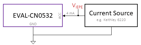
- Solder a twin twisted wire, coaxial or shielded cable to the EVAL-CN0532-EBZ printed circuit board (PCB). Ground line to GND and supply/signal to ACC as shown in the figure below. Note: the output voltage increases if there is a positive acceleration in positive sensitivity axis direction.

- Connect the other end of the cable to an ICP Signal Conditioner (e.g. PCB 482C64), or an IEPE-compatible vibration measurement equipment such as the LMS SCADAS from Siemens or the CompactDAQ from National Instruments (note: in most IEPE compatible DAQ systems, the DC level of the output is eliminated through an AC coupling circuitry). Alternatively, one can use a current source, e.g. Keithley 6220, set the output current to 4 mA, and max voltage to 16 V. The voltage of the current source is the output, as shown in the picture below. Without an external acceleration, the IEPE output should be around 12 V. In this setup the DC level is not removed.
- Set the acceleration sensitivity (40 mV/G) on the vibration measurement equipment from Step 4 to taking data with the accelerometer sensors. The sensitivity scale of the ADXL1002, therefore EVAL-CN0532-EBZ, may slightly vary from part to part. The ADXL1002 can be simply calibrated with gravity field or other reference sensors.
- The EVAL-CN0532-EBZ is ready for experiment.
Mechanical Mounting
The accelerometer used in this reference design, ADXL1002, is an ultra-low noise and high bandwidth sensor. To achieve the best performance, a proper mechanical design is required to deliver vibration signal from the measurement point to the sensor. Careful considerations in design of EVAL-CN0532-EBZ PCB has been taken to avoid vibration signal distortion to the sensor due to mechanical resonance of the PCB structure. To best deliver the vibration signal from the measurement point to the PCB, we have designed EVAL-XLMOUNT1. This mechanical interface is optimized to have a 3dB flat mechanical response of up to 20 kHz. Therefore, by utilization of EVAL-XLMOUNT1, the vibration signal will be adequately coupled with the sensor. The following steps describe how to use EVAL-XLMOUNT1 with EVAL-CN0532-EBZ.
- Using four 4-40 3/8” screws, securely mount the EVAL-CN0532-EBZ to the EVAL-XLMOUNT1 mechanical interface. For optimum performance, use all four screws.
- Firmly mount EVAL-XLMOUNT1 to the vibration platform or shaker table using a M6 or similar diameter screw. Note that the sensitivity direction of the ADXL1002, as shown in the figure above, is aligned with the platform’s main vibration direction.
- Follow steps for proper sensor connection outlined above.
Schematic, PCB Layout, Bill of Materials
EVAL-CN0532-EBZ Design & Integration Files
- Schematics
- PCB Layout
- Bill of Materials
- Allegro Project
End of Document
resources/eval/user-guides/circuits-from-the-lab/cn0532.1614789456.txt.gz · Last modified: 03 Mar 2021 17:37 by Brandon Bushey