


This version (29 Jul 2021 05:14) was approved by Zuedmar Arceo.The Previously approved version (03 Jan 2021 21:56) is available.
Table of Contents
CN0385 Evaluation Board and Software User Guide
Overview
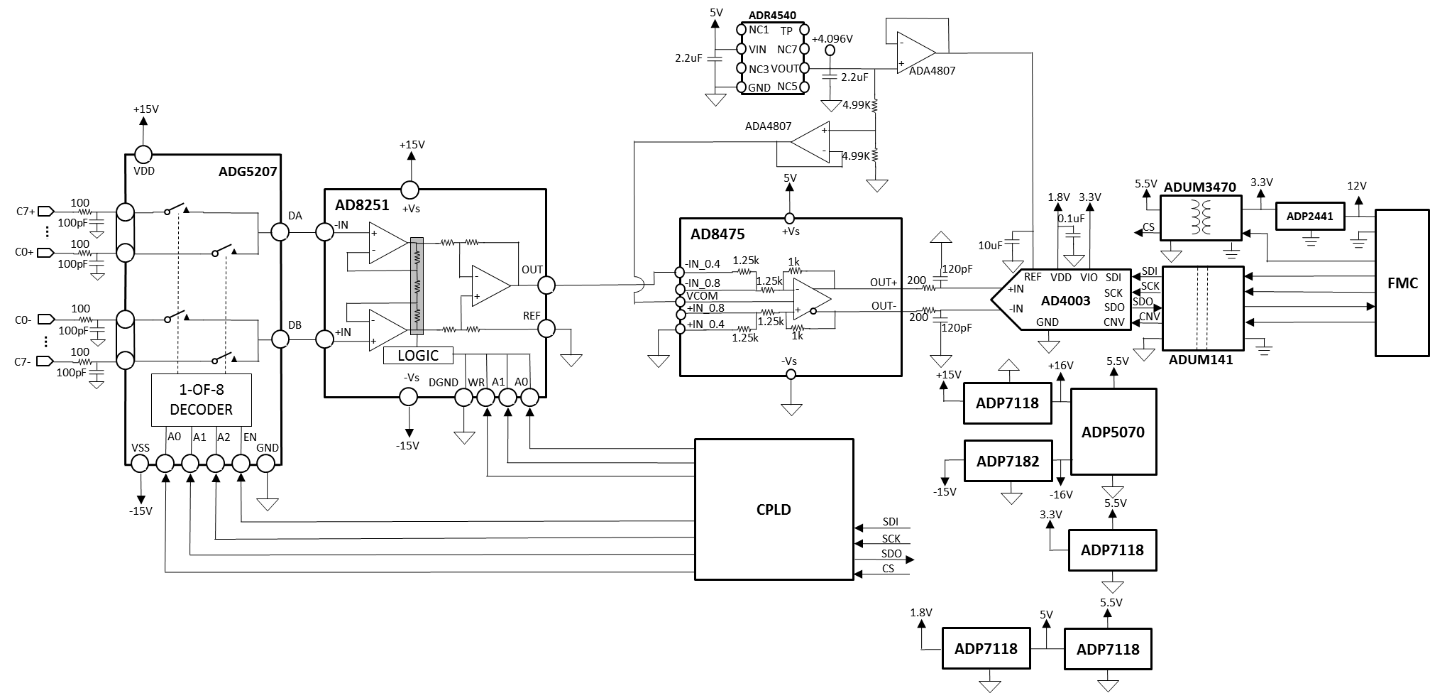
CN0385 is an isolated multichannel data acquisition system that is compatible with standard industrial signal levels. The components are specifically selected to optimize settling time between samples, providing 18-bit performance at channel switching rates up to roughly 750 kHz.
The CN0385 can process eight gain-independent channels and is compatible with both single-ended and differential input signals. The analog front end includes the ADG5207 multiplexer, the AD8251 programmable gain instrumentation amplifier (PGIA), the AD8475 as a precision ADC driver for performing the single-ended-to-differential conversion, and the AD4003, an 18-bit, 2 MSPS Precision ADC. Gain configurations of 0.4, 0.8, 1.6, and 3.2 are available.
The maximum sample rate of the system is 2 MSPS in Turbo Mode for single channel continuous sampling. The channel switching logic is synchronous to the ADC conversions, and the maximum channel switching rate is 1.5 MHz. Channel switching rates up to 100 kHz also provide 18-bit performance.
This user guide will discuss how to operate the EVAL-SDP-CH1Z and the evaluation software to configure and collect data from the EVAL-CN0385-FMCZ Evaluation Board (CN-0385 Board). A complete design support package for the EVAL-CN0385-FMCZ evaluation board containing schematics, layouts (native and Gerber), and bill-of-materials can be found at: CN0385-DesignSupport.
Required Equipment
- EVAL-CN0385-FMCZ Evaluation Board
- EVAL-SDP-CH1Z Controller Board (SDP-H1 Board)
- +5V to +12V power supply or wall wart (+9V wall wart included)
- PC with a USB port and Windows® XP, Windows Vista® (32-bit), or Windows 7, 8 or 10 (32-bit) with .NET 4.0 framework installed (included in installation of SDP Drivers)
- USB type A to USB type mini-B cable
- Precision signal generators/dc sources
General Setup
- The EVAL-CN0385-FMCZ board connects to the EVAL-SDP-CH1Z SDP-H1 Board via the 160-pin connector.
- Refer to the Jumper Settings table for setting the EVAL-CN0385-FMCZ board to the desired power, reference, and signal chain configuration.
- The included +9V power supply connects to P3 on EVAL-CN0345-FMCZ.
- The EVAL-SDP-CH1Z SDP-H1 Board connects to the PC via the USB cable.

Installing the Software
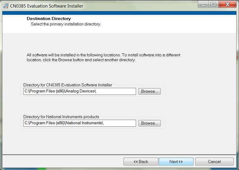
- Download the CN0385 Evaluation Software and unzip the CN0385_Evaluation_Software.zip folder and run setup.exe.


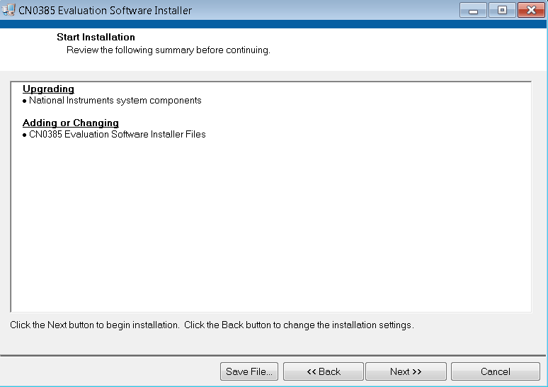
- Click Next to view the installation review page.

- Click Next to start the installation.

- Upon completion of the installation of the CN0385 Evaluation Software, click Next for the installer of the ADI SDP Drivers to execute. (The SDP drivers include an installation of the .NET 4.0 framework.)

- Press Next to set the installation location for the SDP Drivers.

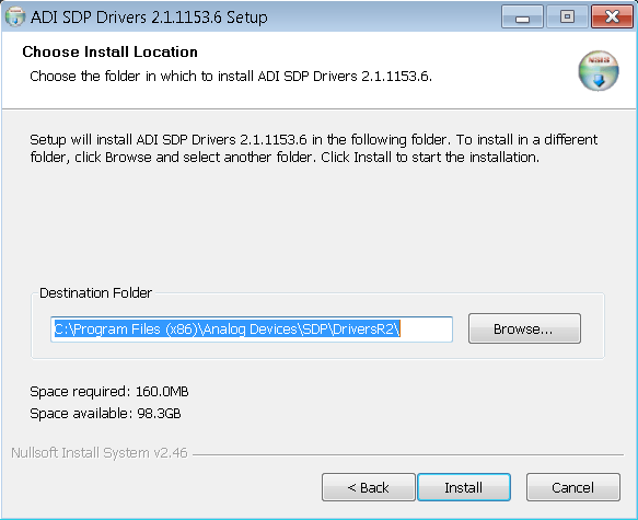
- Press Install to install the SDP Drivers and complete the installation of all software. Click Close when done.


Connecting the Hardware
- Configure the various jumper positions to the desired settings (refer to the Jumper Settings table below)
- Connect P1 of the EVAL-CN0385-FMCZ (CN0385 Evaluation Hardware) to the EVAL-SDP-CH1Z (SDP-H1 Board).
- Connect the included 12V supply to Jack J7 on the EVAL-SDP-CH1Z (SDP-H1 Board) board.
- Connect the USB Cable to J1 on the EVAL-SDP-CH1Z (SDP-H1 Board) board.
- Connect the included 9V supply to P3 on the EVAL-CN0385-FMCZ board.
- Connect the USB Cable to the PC.
Jumper Table
| Jumper Ref Des | Default | Function |
|---|---|---|
| J2 | A | Select external 9V adaptor or bench DC 9V from P3 or J1 |
| S1 | A,B,C,D,E,F,G,H | Differential Inputs for all 8 channels |
Using the Evaluation Software
Software Control and Indicator Descriptions
Front Panel
Configuration Tab

- External REF (V)
- Determines the value of the reference voltage used in calculations and analysis by the software. Affects aspects of the Waveform and Histogram plots (i.e. volt axis values, LSB-to-voltage conversions, etc.). Should be set to the value of the reference voltage used on the EVAL-CN0385-FMCZ Board (4.096 V by default).
- Throughput Rate
- Sets the sample rate of the AD4003 (in KSPS). Note: the effective sample rate for each channel in the sequence (in KSPS) is equal to the value in Sample Rate divided by the number (1, 2, 4, or 8) of channels in the sequence.
- ADC Register Setting
- Set or clear the AD4003 register control bits by click the corresponding button.
- Read ADC Register
- Read back the AD4003 register control bits and OVP bit, and show them in the following LEDs on the right. “1” turns on the LEDs on, and “0” turns the LEDs off.
- ADC Control and Status LEDs
- After Read ADC Register, the control and status bits are assigned to the following LEDs on the right. “1” turns on the LEDs on, and “0” turns the LEDs off.
- MUXSequencerEN
- Set to ON to enable sequence mode, and set to OFF to disable sequence mode and use MUX Channel to select the target channel to sample.
- MUX Channel
- When MUXSequencerEN is OFF, MUX Channel is used to select the target channel to sample; When MUXSequencerEN is On, MUX Channel is used to select the last channel (1, 2, 4, or 8) in the sequencer to sample.
- CHx Gain
- Select the gain for each channel.
- Samples
- Selects the sample number to be performed for each acquisition. If the MUXSequencerEN is ON, it is the sample number for each channel.
- Single Capture
- Initiates a set of conversion samples for each acquisition.
- Continuous Capture
- Initiates multiple sets of conversion samples. Each set of conversions contains a number of samples set and repeats until Continuous Capture is depressed.
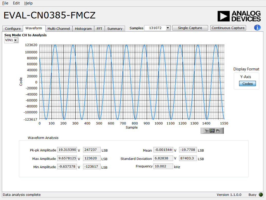
Waveform Tab

- Waveform Plot
- Displays the Waveform of the sampled data.
- Waveform Graph Palette
- Sets the display range of the Multi-Channel Waveform Plot.
- Y-Axis Display Format
- Selects whether the data will be displayed in raw code values or in equivalent voltage in the Plot. Note: code value to voltage conversions are calculated based on the value of VREF in the Configuration Tab.
- Waveform Analysis
- Calculation of the captured samples.
Multi-Channel Tab

- Multi-Channel Waveform Plot
- Displays the Waveform of Displays the data readback from each of the active and visible channels in the conversion sequence.
- Multi-Channel Waveform Graph Palette
- Sets the display range of the Multi-Channel Waveform Plot.
- Multi-Channel Selectors
- Selects which channels' data are visible on the Multi-Channel Waveform Plot. Note: channels must be included in the sequence to be displayed.
- Y-Axis Display Format
- Selects whether the data will be displayed in raw code values or in equivalent voltage in the Plot. Note: code value to voltage conversions are calculated based on the value of VREF in the Configuration Tab.
- Seq Mode CH to Analysis
- Selects the channel for the Waveform Analysis in channel sequencer mode.
- Waveform Analysis
- Calculation of the captured samples.
Histogram Tab

- Waveform Plot
- Displays the occurrences of the sampled codes.
- Waveform Graph Palette
- Sets the display range of the Histogram Plot.
- Histogram Analysis
- Calculation of the captured samples.
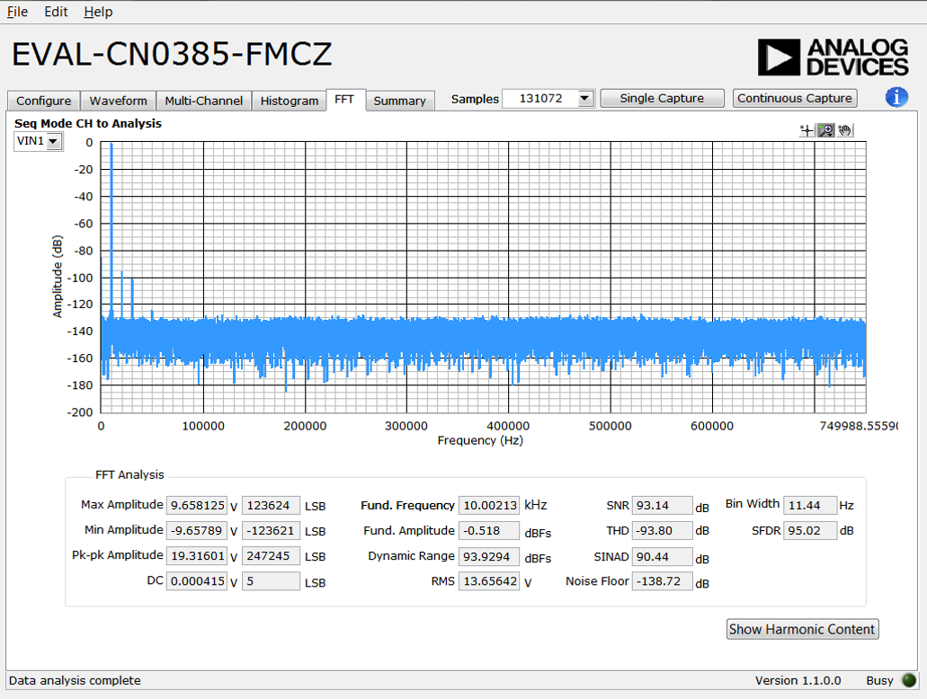
FFT Tab
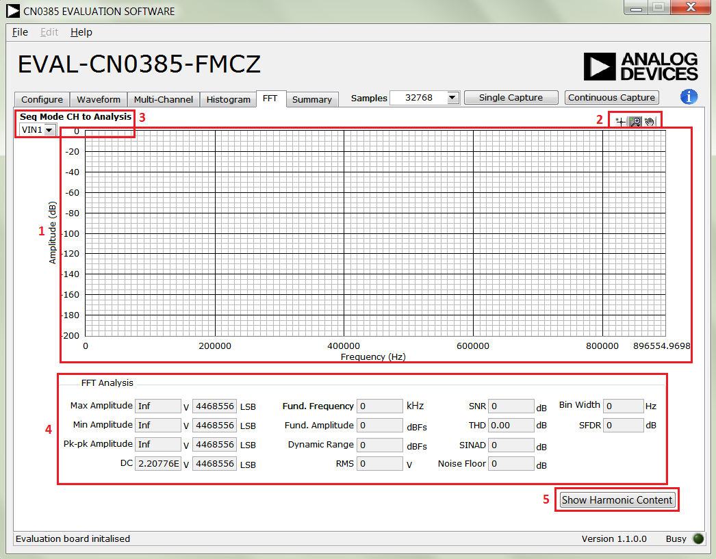
- FFT Spectrum Plot
- Displays the FFT frequency response of the sampled codes.
- Waveform Graph Palette
- Sets the display range of the FFT Plot.
- Seq Mode CH to Analysis
- Selects the channel for the FFT Analysis in sequencer mode.
- FFT Analysis
- Calculation of the captured samples.
- Show Harmonic Content
- Shows the fundamental frequency and 2nd to 5th harmonics.
File
- Save Captured Data
- Saves the current captured samples of the CN0385 Evaluation Software as a .csv file.
- Load Captured Data
- Selects a previously saved samples of CN0385 Evaluation Software.
- Take Screenshot
- Make a capture the CN0385 Evaluation Software GUI and save it as a picture.
- Print Screenshot
- Make a capture the CN0385 Evaluation Software GUI and send it to printer.
- Exit
- Closes the CN0385 Evaluation Software.
Help
- Analog Devices Website
- Opens the Analog Devices, Inc. website http://www.analog.com/ using the PC's current default web browser.
- About
- Displays the current version information of the CN0385 Evaluation Software in a pop-up.
Establishing a USB Connection Link
- Verify that the SDP drivers are properly installed (see Installing the Software).
- Ensure that the CN0385 Evaluation Hardware and the SDP-H1 Controller Board are correctly connected and powered up.
- Run the CN0385 Evaluation Software (CN0385.exe).
- If the CN0385 Evaluation Hardware is properly connected to the PC, the evaluation software will automatically establish a connection with the SDP-H1 Controller Board.
- If the software does not detect the CN0385 Evaluation Hardware, a pop-up will appear with options to reattempt the connection. Selecting Rescan will attempt to establish the USB connection again.

Configuring a Conversion Sequence
Configurations are defined in Configuration tab. Note: In normal mode the max sampling rate is 1.5 MSPS. Only when Turbo Mode is enabled, the sampling rate can go up to 2 MSPS. Turn MUXSequencerEN ON to enable the sequencer for multi-channel sampling. In the sequencer mode, it can only convert in sequence from channel 1 to the last channel in defined by MUX Channel.
Capturing Samples
After the configuration is done and the CN0385 Evaluation Hardware and Software are connected, the software can initiate conversions. To capture samples:
- Ensure that the value in VREF matches the reference voltage being used on the CN0385 Evaluation Hardware. Note that, the Sample Rate is the sample rate of the AD4003, not the effective sample rate for each channel.
- Select the desired Sample Rate and SCK rate.
- Note that the Sample Rate is the sample rate of the AD7982, not the effective sample rate for each channel.
- Press either Single Capture to perform a single burst of sampling sequences or Continuous Capture to perform repeated bursts of sampling sequences until stopped.
Viewing Conversion Results
After capturing samples or loading a previous set of conversion results, the data and analysis items for each channel can be viewed using the Waveform tab, the Histogram tab, the FFT tab and the Summary tab.
- Select the Multi-Channel tab to view every channel's data on a single plot. The Multi-Channel Selectors set the visibility of each channel's data.

- Select the Waveform tab to view the sampled channel's data or analysis results in non-sequencer mode. The Histogram and FFT sub-tabs show the dc and ac analysis.

Registration
Receive software update notifications, documentation updates, view the latest videos, and more when you register your hardware. Register to receive all these great benefits and more!
End of Document
resources/eval/user-guides/circuits-from-the-lab/cn0385.txt · Last modified: 29 Jul 2021 05:14 by Zuedmar Arceo