


This version (29 Jul 2021 07:47) was approved by Harvey John De Chavez.The Previously approved version (03 Jan 2021 22:03) is available.
Table of Contents
CN0355 Software User Guide
Overview
The circuit is a complete low power signal conditioner for a bridge-type sensor and includes a temperature compensation channel. It is ideal for a variety of industrial pressure sensors and load cells that operate with drive voltages between 5 V and 15 V.
The circuit can process full-scale signals from approximately 10 mV to 1 V using the internal PGA of the 24-bit sigma-delta ADC, making it suitable for a wide variety of pressure sensors.
The entire circuit uses only three ICs and requires only 1 mA (excluding the bridge current). A ratiometric technique ensures that the accuracy and stability of the system does not depend on a voltage reference.
General Setup
- EVAL-CN0355-PMDZ Evaluation Board
- EVAL-SDP-CB1Z Evaluation Board
- SDP-PMD-IB1Z Evaluation Board
- CN0355 Evaluation Software(supplied with provided CD in kit)
- +6V DC power supply
- USB Type-A plug to USB Mini-B plug cable
- Honeywell (Mfg #:NSCSANN600MGUNV)
- 2/3/4-Wire RTD sensor
NOTE: an RTD sensor can be bypassed by shorting P9 connector that can be seen in the EVAL-CN0355-PMDZ Evaluation Board
Minimum PC/System Requirements
- One PC with the following
- Windows XP SP2, Windows Vista or Windows 7 Business/Enterprise/Ultimate editions
- Intel Pentium processor (x86 compatible), 1GHz or faster
- 512 MB RAM and 2 GB available hard disk space
- .NET 3.5 Framework
How to Install the Evaluation Software
- Extract the file CN0355 Eval Software.zip and open the file setup.exe.
NOTE: It is recommended that you install the CN0355 Evaluation Software to the default directory path C:\Program Files\Analog Devices\CN0355\ and all National Instruments products to C:\Program Files\National Instruments\

- Click “Next” to view the installation review page
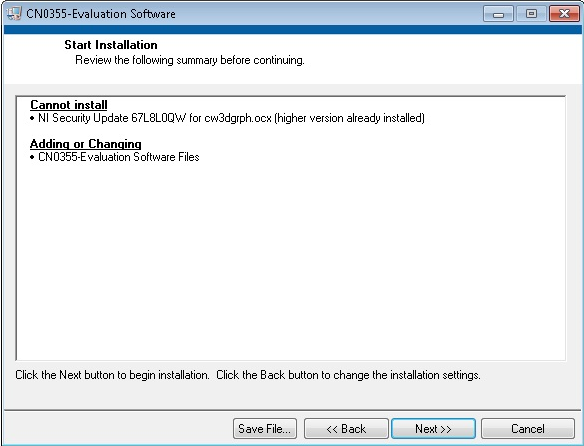
- Click “Next” to start the installation

- Upon completion of the installation of the CN0355 Evaluation Software, the installer for the ADI SDP Drivers will execute.

- Click “Next” to finish the installation.

- Click “Next” to set the installation location for the SDP Drivers.
NOTE: It is recommended that you install the drivers to the default directory path C:\Program Files\Analog Devices\SDP\Drivers

- Press “Next” to install the SDP Drivers and complete the installation of all software.
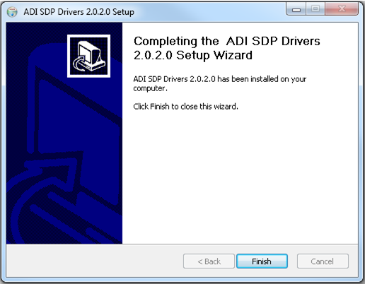
- Click “Finish” when done.


STEP BY STEP INSTRUCTION FOR CONNECTING THE HARDWARE

- Plug the mini end of the USB cable into connector J1 of the EVAL-SDP-CB1Z and connect the other end of the USB cable into the Laptop or PC.
- Connect the 120-pin connector of the SDP-PMD-IB1Z circuit board to the connector marked “CON A” on the EVAL-SDP-CB1Z evaluation (SDP) board. Nylon hardware should be used to firmly secure the two boards, using the holes provided at the ends of the 120-pin connectors.
- Populate a jumper across JP1 to give +3.3V voltage out in PMOD terminal as seen in the label found in SDP-PMD-IB1Z.
- Connect the 12-pin right angle male pin header of EVAL-CN0355-PMDZ to the 12-pin right angle female pin header of SDP-PMD-IB1Z.
- Connect the +6V DC power supply or an equivalent power supply to JP1, the barrel jack wallwart terminal of the SDP-PMD-IB1Z interposer board.
- Connect the RTD sensor in P2 of EVAL-CN0355-PMDZ.
- Set P3 and P4 jumper configuration according to the type of RTD sensor that will be used to evaluate the sensor
NOTE: jumper pin configuration to set up the RTD sensor can be seen at the back of EVAL-CN0355-PMDZ eval board.
- Connect the Pressure transducer in P1 of EVAL-CN0355-PMDZ.
- Set P5, P6 and P7 jumper configuration to the desired Bridge type transducer voltage drive
NOTE: jumper pin configuration to set up the Bridge type transducer voltage drive can be seen at the back of EVAL-CN0355-PMDZ eval board.
- Plug in the wall wart and connect it to connector P8 of the EVAL-CN0355-PMDZ.
RTD AND BRIDGE TYPE TRANSDUCER INTERFACING DIAGRAM

OPENING AND ENABLING THE EVALUATION SOFTWARE

- Launch the executable found at C:\Program Files\Analog Devices\CN0355.
- Click the “Run” button in order to start using the program
- After clicking the “Run” button, a prompt will appear informing the user that the SDP is now ready to acquire data and the rest of the buttons found in System Controls will be enabled.
STEP BY STEP INSTRUCTION USING THE EVALUATION SOFTWARE

Below are the list of available software controls grouped according to their location in the software GUI:
- System Controls
- Run – This button configures the AD7793 by writing to the necessary registers. A prompt will appear informing the user if the ADC was properly configured.
- Stop – Halt or pause data acquisition. Resumes when ‘Run’ button is press again.
- Save Data – This button saves all data displayed in the LabVIEW chart.
- Clear Data – This button clears all data displayed in the LabVIEW chart.
- Main Tab – This tab contains the displays for the Data Graph, System and SDP Board Firmware Revision.
- Data Graph – This page contains a waveform chart visually displaying the pressure readings and the temperature readings taken after performing system calibration.
- System Calibration – This page contains the controls necessary to calibrate the entire system using either 2-point or 4-point linear interpolation. This also contains the settings for the ADC data rate and RTD values.
- ADC and RTD Setting – This option gives the user capability to set the ADC data rate and the flexibility to use different values of RTD by plugging in the values in the given input box under RTD Value.
- Calibration Options – This option defines the calibration type to be performed.
NOTE: The chosen calibration settings will be enabled for configuration and the other calibration will be disabled and greyed out.
- 2 – Point Calibration – This button defines the values of the parameters to be used to calculate for the pressure read by the transducer using two data points calibration system without temperature compensation.
- Voltage Drive – Defines the voltage use to drive the bridge type transducer.
- Operating Range
- Minimum Range – Determines the minimum operating pressure range of the transducer.
- Maximum Range – Determines the maximum operating pressure range of the transducer.
- Sensitivity – gives the mV sensitivity of the device over the defined voltage drive specified at a full scale span.
NOTE: This information can be found in the transducer datasheet
- 4 – Point Calibration – This button defines the values of the parameters to be used to calculate for the pressure read by the transducer using four data points calibration system with temperature compensation.
- Pressure 1 – define the first pressure value point.
- Pressure 2 – define the second pressure value point.
- Pressure Full Scale – define the maximum operating pressure range.
- Set Calibration Point @ temp 1 – by clicking this button it captures the voltage reading generated at the transducer specified at temp 1 and at a defined pressure value set in the Pressure Settings.
- Pressure Settings
- Pressure 1 @ temp 1 – set the first point of the calibration taken at temp 1 and pressure set at pressure 1.
- Pressure 2 @ temp 1 – set the second point of the calibration taken at temp 1 and pressure set at pressure 2.
- Set Calibration Point @ temp 2 – captures the voltage reading generated at the transducer specified at temp 2 and defined pressure settings by clicking this button.
- Pressure Settings
- Pressure 1 @ temp 2 – set the third point of the calibration taken at temp 2 and pressure set at pressure 1.
- Pressure 2 @ temp 2 – set the fourth point of the calibration taken at temp 2 and pressure set at pressure 2.
- Save or Load Cal Settings – this allows the user to save setup by clicking the Save button or recall the calibration setup formatted in an .xls file.
- To save the calibration settings, click Save button then choose the desired location and provide a file name with an extension filename of .xls to create new file or click an existing file with a .xls extension to over write it with a new data.
- To recall the calibration setting, click the folder to browse for the location of the file that contains the calibration settings and click Load Calibration to change the calibrations settings indicated in the file that was loaded.
- SDP Board Firmware Revision – provides details on the firmware version of the Blackfin used by the SDP board.
CALIBRATION PROCEDURE
This section explains the steps required to properly calibrate the EVAL-CN0355-PMDZ.
Pre-Calibration Note:
- Choose the desired calibration option
- 2 – point calibration does not require temperature oven to calibrate the system. It only requires the table to be filled-in with numbers from the datasheet.
- 4 – point calibration requires an oven with calibrated temperature sensor and calibrated pressure source.
- Dwell time of the temperature depends on the equipment that is being used to calibrate the system.
- The voltage drive set in the evaluation software should correspond to the configured jumper set up found in EVAL-CN0355-PMDZ.
- All units is in PSI
- Sensitivity is usually found in the datasheet of the transducer to be used.
2 – Point Calibration
Step 1 - Set the voltage use to drive the transducer.
Step 2 - Set the minimum and maximum operating range of the sensor in PSI.
Step 3 - Set the sensitivity of the transducer that will be used.
Step 4 - Go to Data Graph panel to view the measurement.
4 – Point Calibration
Step 1 - Define any two known pressure points where the calibration condition will be done and where the 4 – points will define.
Step 2 - Set the temperature chamber at temp 1.
Step 3 - Under the options on Pressure Setting, choose ‘Pressure 1 @ temp 1’ while the pressure at the chamber is set to the stated value in Pressure 1.
Step 4 - Click ‘Set Calibration Point @ temp 1’ button to read the voltage generated by the transducer and the temperature voltage generated across the RTD.
Step 5 - Set the chamber pressure to the stated value in Pressure 2 and then choose ‘Pressure 2 @ temp 1’ under the options on Pressure Setting.
Step 6 - Click ‘Set Calibration Point @ temp 1’ button to read the voltage generated by the transducer and the temperature voltage generated across the RTD.
Step 7 - Click ‘Set Calibration Point @ temp 1’ button to read the voltage generated by the transducer.
Step 8 - Set the temperature chamber at temp 2.
Step 9 - Do Step 3 to Step 7 under column Temperature 2.
Registration
Receive software update notifications, documentation updates, view the latest videos, and more when you register your hardware. Register to receive all these great benefits and more!
resources/eval/user-guides/circuits-from-the-lab/cn0355.txt · Last modified: 29 Jul 2021 07:47 by Harvey John De Chavez