


This version is outdated by a newer approved version. This version (31 Jan 2013 17:34) is a draft.
Approvals: 0/1
This version (31 Jan 2013 17:34) is a draft.Approvals: 0/1
This is an old revision of the document!
Table of Contents
CN0288 Software User Guide
Overview
CN0288 is a linear variable differential transformer (LVDT) signal conditioning circuit. The system converts the output of the LVDT sensor to a unipolar DC voltage and drives the inputs of a successive approximation analog-to-digital converter (ADC).
This circuit uses a single chip solution that drives the excitation signal of the primary side of the LVDT and converts the secondary side. The complete system uses a 12-bit ADC resulting in a dynamic range of 82dB at a standard LVDT bandwidth of 250Hz. (The term bandwidth used in this case is referring to a sinusoidally varying mechanical position and can be easily configured to meet wider bandwidth applications by configuring a few external passive components.)
The signal conditioning circuitry of the system consumes only 15mA of current from the ±15V supply and 3mA from the +5V supply making this configuration suitable for industrial precision position and gauging applications such as flight control surface position feedback.
This circuit note discusses the design steps needed to optimize the circuit shown in Figure 1 for a specific bandwidth including noise analysis and component selection considerations.
This user guide will discuss how to use the evaluation software to collect data from the EVAL-CN0288-SDPZ Daughter Board

Required Equipment
- EVAL-SDP-CB1Z Evaluation Board (SDP-B Board)
- EVAL-CN0288-SDPZ Daughter Board (CN0288 Board)
- EVAL-CFTL-6V-PWRZ Power Supply or equivalent +6V power supply
- EVAL-CFTL-LVDT Linear Variable Differential Transformer (Measurement Specialties, Inc. E-100 Economy Series LVDT)
-
- (supplied with provided CD in kit)
- PC with the following Minimum Requirements
- Windows XP Service Pack 2 (32-bit)
- USB type A Port
- Processor rated at 1GHz or faster
- 512 MB RAM and 500 MB available hard disk space
- USB type A to USB type mini-B cable
General Setup
- The EVAL-CN0288-SDPZ Evaluation Board connects to the EVAL-SDP-CB1Z SDP-B Board via the 120-Pin connector
- The EVAL-CFTL-6V-PWRZ DC power supply powers the EVAL-CN0288-SDPZ Board via the DC barrel jack
- The EVAL-SDP-CB1Z SDP-B Board connects to the PC via the USB cable.
- The EVAL-CFTL-LVDT (Measurement Specialties, Inc. E-100 Economy Series LVDT) connects to the EVAL-CN0288-SDPZ Evaluation Board via the 6-pin header at J3.
<html><br><br></html> <html><hr></html>
Installing the Software
- Extract the file CN0288 Eval Software.zip and open the file setup.exe.<html><br><br></html>
NOTE: It is recommended that you install the CN0288 Evaluation Software to the default directory path C:\Program Files\Analog Devices\CN0288\ and all National Instruments products to C:\Program Files\National Instruments\
<html><br><br><br><br><br></html>

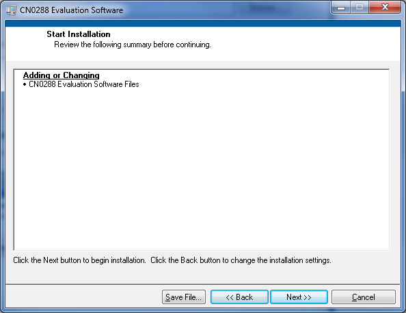
- Click Next to view the installation review page<html><br><br></html>
 <html><br><br></html>
 - Click Next to start the installation<html><br><br></html>
 <html><br><br></html>
 - Upon completion of the installation of the CN0288 Evaluation Software, the installer for the ADI SDP Drivers will execute.<html><br><br></html>
NOTE: It is recommended that you close all other applications before clicking “Next”. This will make it possible to update relevant system files without having to reboot your computer.
<html><br><br></html>
 <html><br><br></html>
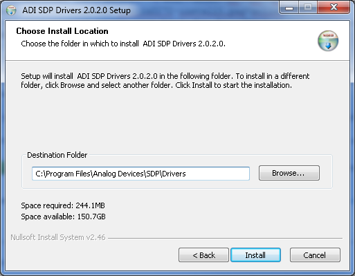
- Press “Next” to set the installation location for the SDP Drivers.<html><br><br></html>
It is recommended that you install the drivers to the default directory path <html><br></html>C:\Program Files\Analog Devices\SDP\Drivers
<html><br><br></html>
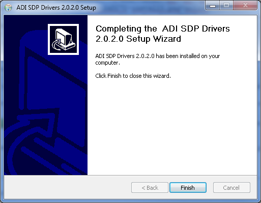
- Press “Next” to install the SDP Drivers and complete the installation of all software. Click “Finish” when done.<html><br><br></html>
<html><hr></html>
Connecting the Hardware
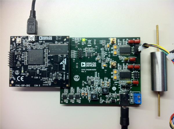
- Connect the EVAL-CFTL-LVDT (Measurement Specialties, Inc. E-100 Economy Series LVDT) as depicted in the figure below.<html><br><br></html>
NOTE: If a different LVDT is used other than the E-100 LVDT from Measurement Specialties, Inc the wiring schematic will be different
<html><br><br></html>
 <html><br><br></html>
 <html><br><br><br><br><br><br><br><br><br><br><br></html>
- Connect J3 of the EVAL-CN0288-SDPZ (CN0288 Board) to the cable assembly of the EVAL-CFTL-LVDT (Measurement Specialties, Inc. E-100 Economy Series)<html><br><br></html>
 <html><br><br></html>
 - Connect J8 of the EVAL-CN0288-SDPZ (CN0288 Board) to CON A of the EVAL-SDP-CB1Z (SDP-B Board)<html><br><br></html>
 <html><br><br></html>
 - Connect a +6V supply to the Barrel Jack at J4 or the Screw Terminal at J1 on the CN0288 Board<html><br><br></html>
 <html><br><br></html>
 - Connect the USB cable to J1 of the EVAL-SDP-CB1Z (SDP-B Board)<html><br><br></html>
 <html><br><br></html>


<html><hr></html>
Using the Evaluation Software
Software Control and Indicator Descriptions

- <html><a id=“1”><b>SDP Connector Dropdown Menu</b></a></html>
- This control will select which connector (on the SDP-B Board) the CN0288 Board is currently connected to. The options are “connectorA” or “connectorB”. The connector to be used must be selected before clicking the <html><a href=“#2”><b>Connect to SDP-B Board Button</b></a></html>
- <html><a id=“2”><b>Connect to SDP-B Board Button</b></a></html>
- When this button is pressed, the SDP-B Board makes a USB connection to the CN0288 Board. A connection to the SDP-B Board must be made to use the software. This button is also used in conjuction with the <html><a href=“#1”><b>SDP Connector Dropdown Menu</b></a></html>.
- <html><a id=“3”><b>Take Snapshot(s) Button</b></a></html>
- When this button is pressed, the SDP-B Board will collect a single Snapshot or a collection of Snapshots depending on the <html><a href=“#5”><b>Acquisition Mode</b></a></html> setting.<html><br><br></html>
Snapshot - a collection of analog to digital conversions, sampled at 20MSPS, acquired by the SDP-B Board and displayed in the graph.
<html><br><br><br><br><br><br></html>
- <html><a id=“4”><b>Save Snapshot(s) Button</b></a></html>
- When this button is pressed, the software will save a single Snapshot or a collection of Snapshots to a tab delimited ASCII spreadsheet file.
- <html><a id=“5”><b>Acquisition Mode Radio Buttons</b></a></html>
- Single Snapshot - When the software is in this mode, the SDP-B Board will collect a single Snapshot of data.
- Multiple Snapshots - When the software is in this mode, the SDP-B Board will collect multiple Snapshots of data.
- <html><a id=“6”><b>Conversions in Snapshot Numerical Control</b></a></html>
- This control determines the number of conversions in a single Snapshot of data.
- The minimum value is 1 and the maximum value is 65,536.
- <html><a id=“7”><b>Snapshots to Take Numerical Control</b></a></html>
- This control determines the number of Snapshots of data the SDP-B Board collects.
- The minimum value is 1 and the maximum is 65,536
- This control is only enabled in Multiple Snapshots Acquisition Mode.
- <html><a id=“8”><b>Snapshot Delay (ms) Numerical Control</b></a></html>
- This control determines the delay (in milliseconds) between Snapshots.
- The minimum value is 1 and the maximum value is 65,536
- This control is only enabled in Multiple Snapshots Acquisition Mode.
- <html><a id=“9”><b>Control Tabs</b></a></html>
- Photocurrent Results - Clicking this tab brings the Photocurrent Results graph to the front
- Histogram Results - Clicking this tab brings the Histogram Results graph to the front
- Configure - Clicking this tab brings the System Settings to the front
- <html><a id=“10”><b>Graph Controls</b></a></html>
- These controls allow the user to zoom-in, zoom-out, and pan through the Snapshot displayed.
- <html><a id=“11”><b>Graph Units Radio Buttons</b></a></html>
- This control determines the Y-Axis units of the “Snapshot” displayed in the graph.
- <html><a id=“12”><b>Snapshot Displayed Numerical Control/Indicator</b></a></html>
- This control determines the current Snapshot to display in the graph. When the value is changed, the graph is updated with the Snapshot specified.
- This control also acts as an indicator of the current Snapshot displayed in the graph. For example, when the software is in the process of collecting multiple Snapshots, the indicator is incremented as the Snapshots are collected.
- This control/indicator is only enabled in Multiple Snapshots Acquisition Mode.
- <html><a id=“13”><b>System Status String Indicator</b></a></html>
- This indicator displays a message to the user detailing the current state of the software.
Establishing a USB Connection Link
- Follow the instructions to properly install the software and connect the hardware as described in the previous sections.
- Open the file named CN0288.exe in the installation directory.<html><br><br></html>
NOTE: If the software was installed to the default location it will be found at <html><br></html>C:\Program Files\Analog Devices\CN0288\CN0288.exe
<html><br><br><br><br><br><br></html>
- Select the connector to use from the <html><a href=“#1”><b>SDP Connector Dropdown Menu</b></a></html>.
- Click the <html><a href=“#2”><b>Connect to SDP-B Board Button</b></a></html>. A window with a progress bar will load.<html><br><br></html>
 <html><br><br></html>
 - Upon success, the <html><a href=“#13”><b>System Status String Indicator</b></a></html> will display SDP-B Ready to Take Snapshot(s)<html><a id=“ssnap”><br></a></html>
resources/eval/user-guides/circuits-from-the-lab/cn0288.1359650090.txt.gz · Last modified: 31 Jan 2013 17:34 by James Fitzgerald