


This version (29 Jul 2021 06:04) was approved by Harvey John De Chavez.The Previously approved version (03 Jan 2021 21:55) is available.
Table of Contents
CN-0272 Software User Guide
Overview
CN-0272 is a high-speed photodiode signal conditioning circuit with dark current compensation. The system converts current from a high-speed silicon PIN photodiode and drives the inputs of a 20 MSPS ADC. This combination of parts offers spectral sensitivity from 400 nm to 1050 nm with 49 nA of photocurrent sensitivity, a dynamic range of 91 dB and 2 MHz of bandwidth. The signal conditioning circuitry of the system consumes only 40 mA of current from the ±5 V supplies making this configuration suitable for portable high-speed high-resolution light intensity applications such as pulse oximetry.
Other suitable applications for this circuit would be as an analog opto-isolator. It can also be adapted to applications that require larger bandwidth and less resolution such as adaptive speed control systems.
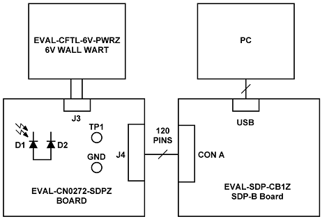
This user guide will discuss how to use the evaluation software to collect data from the EVAL-CN0272-SDPZ Daughter Board

Required Equipment
- EVAL-SDP-CB1Z Evaluation Board (SDP-B Board)
- EVAL-CN0272-SDPZ Daughter Board (CN0272 Board)
- EVAL-CFTL-6V-PWRZ Power Supply or equivalent +6V power supply
-
- (supplied with provided CD in kit)
- PC with the following Minimum Requirements
- Windows XP Service Pack 2 (32-bit)
- USB type A Port
- Processor rated at 1GHz or faster
- 512 MB RAM and 500 MB available hard disk space
- USB type A to USB type mini-B cable
- Light source between 400nm to 1050nm (not included in kit)
- SMB Connector (not required)
- This is needed if an external voltage bias for the photodiode is to be used
General Setup
- The EVAL-CN0272-SDPZ Board connects to the EVAL-SDP-CB1Z SDP-B Board via the 120-Pin connector
- The EVAL-CFTL-6V-PWRZ DC power supply powers the EVAL-CN0272-SDPZ Board via the DC barrel jack
Installing the Software
- Extract the file CN0272 SDP Eval Software.zip and open the file setup.exe.
NOTE: It is recommended that you install the CN0272 SDP Evaluation Software to the default directory path C:\Program Files\Analog Devices\CN0272\ and all National Instruments products to C:\Program Files\National Instruments\

- Click Next to view the installation review page
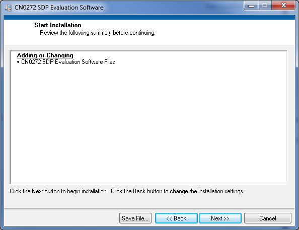
- Click Next to start the installation
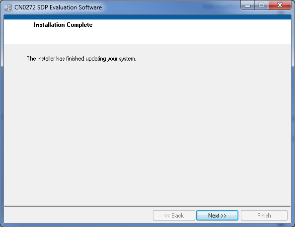
- Upon completion of the installation of the CN0272 SDP Eval Software, the installer for the ADI SDP Drivers will execute.
NOTE: It is recommended that you close all other applications before clicking “Next”. This will make it possible to update relevant system files without having to reboot your computer.
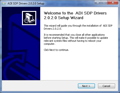
- Press “Next” to set the installation location for the SDP Drivers.
It is recommended that you install the drivers to the default directory path
C:\Program Files\Analog Devices\SDP\Drivers
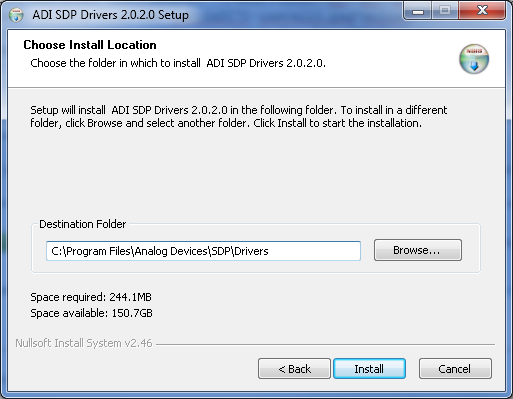
- Press “Next” to install the SDP Drivers and complete the installation of all software. Click “Finish” when done.

Connecting the Hardware
- Select the voltage bias of the photodiode.
- Select the onboard -5V bias by populating JP1 with a shorting jumper as depicted below

- Select an external voltage bias by populatign JP1 with a shorting jumper as depicted below.
NOTE: When using an external voltage to bias the photodiode, a SMB connector also must be connected to J2. The other end of this cable must connect to a voltage supply ≤ 15V.

- Connect a 6V supply to the Barrel Jack or the Screw Terminal on the CN0272 Board

- Connect the USB Cable to the SDP-B Board and the PC


Using the Evaluation Software
Software Control and Indicator Descriptions

- SDP Connector Dropdown Menu
- This control will select which connector (on the SDP-B Board) the CN0272 Board is currently connected to. The options are “connectorA” or “connectorB”. The connector to be used must be selected before clicking the Connect to SDP-B Board Button
- Connect to SDP-B Board Button
- When this button is pressed, the SDP-B Board makes a USB connection to the CN0272 Board. A connection to the SDP-B Board must be made to use the software. This button is also used in conjunction with the SDP Connector Dropdown Menu.
- Take Snapshot(s) Button
- When this button is pressed, the SDP-B Board will collect a single Snapshot or a collection of Snapshots depending on the Acquisition Mode setting.
Snapshot - a collection of analog to digital conversions, sampled at 20MSPS, acquired by the SDP-B Board and displayed in the graph.
- Save Snapshot(s) Button
- When this button is pressed, the software will save a single Snapshot or a collection of Snapshots to a tab delimited ASCII spreadsheet file.
- Acquisition Mode Radio Buttons
- Single Snapshot - When the software is in this mode, the SDP-B Board will collect a single Snapshot of data.
- Multiple Snapshots - When the software is in this mode, the SDP-B Board will collect multiple Snapshots of data.
- Conversions in Snapshot Numerical Control
- This control determines the number of conversions in a single Snapshot of data.
- The minimum value is 1 and the maximum value is 65,536.
- Snapshots to Take Numerical Control
- This control determines the number of Snapshots of data the SDP-B Board collects.
- The minimum value is 1 and the maximum is 65,536
- This control is only enabled in Multiple Snapshots Acquisition Mode.
- Snapshot Delay (ms) Numerical Control
- This control determines the delay (in milliseconds) between Snapshots.
- The minimum value is 1 and the maximum value is 65,536
- This control is only enabled in Multiple Snapshots Acquisition Mode.
- Control Tabs
- Photocurrent Results - Clicking this tab brings the Photocurrent Results graph to the front
- Histogram Results - Clicking this tab brings the Histogram Results graph to the front
- Configure - Clicking this tab brings the System Settings to the front
- Graph Controls
- These controls allow the user to zoom-in, zoom-out, and pan through the Snapshot displayed.
- Graph Units Radio Buttons
- This control determines the Y-Axis units of the “Snapshot” displayed in the graph.
- Snapshot Displayed Numerical Control/Indicator
- This control determines the current Snapshot to display in the graph. When the value is changed, the graph is updated with the Snapshot specified.
- This control also acts as an indicator of the current Snapshot displayed in the graph. For example, when the software is in the process of collecting multiple Snapshots, the indicator is incremented as the Snapshots are collected.
- This control/indicator is only enabled in Multiple Snapshots Acquisition Mode.
- System Status String Indicator
- This indicator displays a message to the user detailing the current state of the software.
- System Status LED Indicator
- This indicator displays the current state of the software in the form of an LED. There are four status LED colors.
 Inactive
 Busy
Busy
 ADC in Power-Down
 Error
Error
Establishing a USB Connection Link
- Follow the instructions to properly install the software and connect the hardware as described in the previous sections.
- Open the file named CN0272.exe in the installation directory.
NOTE: If the software was installed to the default location it will be found at
C:\Program Files\Analog Devices\CN0272\CN0272.exe
- Select the connector to use from the SDP Connector Dropdown Menu.
- Click the Connect to SDP-B Board Button. A window with a progress bar will load.
- Upon success, the System Status String Indicator will display SDP-B Ready to Take Snapshot(s)
Capturing a Single Snapshot
- Establish a USB Connection Link.
- Select Single Snapshot as the Acquisition Mode
- Set the number of conversions in the snapshot
- Click the Take Snapshot(s) Button
Capturing Multiple Snapshots
- Establish a USB Connection Link.
- Select Multiple Snapshots as the Acquisition Mode.
- Set the number of conversions in each snapshot.
- Set the number of snapshots to take.
- Set the snapshot delay.
- Click the Take Snapshot(s) Button.
Displaying a Specific Snapshot
- Establish a USB Connection Link.
- Select Multiple Snapshots as the Acquisition Mode.
- Set the number of conversions in each snapshot.
- Set the number of snapshots to take.
- Set the snapshot delay.
- Click the Take Snapshot(s) Button.
- Type the number of the snapshot of interest into the Snapshot Displayed Numerical Control
Saving a Single Snapshot to a Spreadsheet File
- Establish a USB Connection Link.
- Capture a Single Snapshot.
- Click the Save Snapshot(s) Button.
- Select either Microamps (µA) or ADC Codes.

- Click the OK Button.
- Browse to the directory location where the spreadsheet file is to be saved.
- Name the file.
- Click the OK Button.
The software saves the spreadsheet file as ASCII text with columns separated by tabs.
Saving Multiple Snapshots to a Spreadsheet File
- Establish a USB Connection Link.
- Capture Multiple Snapshots.
- Click the Save Snapshot(s) Button.
- Select either All Snapshots or Range of Snapshot(s).
- If Range of Snapshot(s) is selected, input the subset of snapshots to be saved.
- Select either Microamps (µA) or ADC Codes.
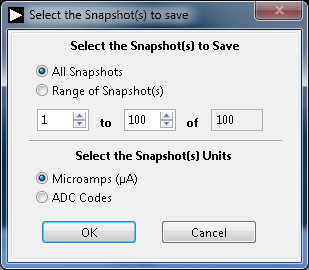
- Click the OK button.
- Browse to the directory location where the spreadsheet file is to be saved.
- Name the file.
- Click the OK Button.
The software saves the spreadsheet file as ASCII text with columns separated by tabs.
Registration
Receive software update notifications, documentation updates, view the latest videos, and more when you register your hardware. Register to receive all these great benefits and more!
resources/eval/user-guides/circuits-from-the-lab/cn0272.txt · Last modified: 29 Jul 2021 06:04 by Harvey John De Chavez