


This version is outdated by a newer approved version. This version (13 May 2013 19:18) was approved by James Fitzgerald.The Previously approved version (01 Apr 2013 23:40) is available.
This version (13 May 2013 19:18) was approved by James Fitzgerald.The Previously approved version (01 Apr 2013 23:40) is available.This is an old revision of the document!
Table of Contents
CN-0271 Software User Guide
Overview
CN-0271 is a complete thermocouple signal conditioning circuit with cold junction compensation followed by a 16-bit sigma-delta (Σ-Δ) analog-to-digital converter (ADC). The AD8495 thermocouple amplifier provides a simple, low cost solution for measuring K type thermocouple temperatures, including cold junction compensation.
A fixed gain instrumentation amplifier in the AD8495 amplifies the small thermocouple voltage to provide a 5 mV/°C output. The high common-mode rejection of the amplifier blocks commonmode noise that the long thermocouple leads can pick up. For additional protection, the high impedance inputs of the amplifier make it easy to add extra filtering.
The AD8476 differential amplifier provides the correct signal levels and common-mode voltage to drive the AD7790 16-bit, Σ-Δ ADC.
The circuit provides a compact low cost solution for thermocouple signal conditioning and high resolution analog-to-digital conversion.
This user guide will discuss how to use the evaluation software to collect data from the EVAL-CN0271-SDPZ Evaluation Board (CN-0271 Board)

Required Equipment
- EVAL-SDP-CB1Z Controller Board (SDP-B Board)
- EVAL-CN0271-SDPZ Evaluation Board (CN-0271 Board)
- EVAL-CFTL-6V-PWRZ +6V Power Supply or equivalent DC Power Supply
- PC with the following Minimum Requirements
- Windows XP Service Pack 2 (32-bit)
- USB Type-A Port
- Processor rated at 1GHz or faster
- 512 MB RAM and 500 MB available hard disk space
- USB Type-A to USB Mini-B cable
- K-Type Thermocouple millivolt source
- K-Type thermocouple male-to-male cable
General Setup
- The EVAL-CN0271-SDPZ (CN-0271 Board) connects to the EVAL-SDP-CB1Z (SDP-B Board) via the 120-Pin connector at J3.
- The EVAL-CFTL-6V-PWRZ +6V power supply powers the EVAL-CN0271-SDPZ (CN-0271 Board) via the DC Barrel Jack at J5 or the screw terminal at J4.
- The EVAL-SDP-CB1Z (SDP-B Board) connects to the PC via the USB cable.
- The thermocouple connects to the EVAL-CN0271-SDPZ (CN-0271 Board) via the thermocouple connector at J1.
 <html><hr></html>
Installing the Software
- Extract the file CN0271 SDP Eval Software.zip and open the file setup.exe.
NOTE: It is recommended that you install the CN-0271 Evaluation Software to the default directory path C:\Program Files\Analog Devices\CN0271\ and all National Instruments products to C:\Program Files\National Instruments\
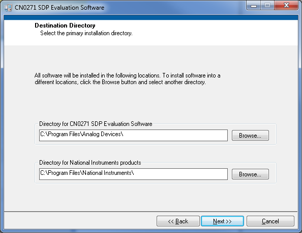
- Click Next to view the installation review page

- Click Next to start the installation

- Upon completion of the installation of the CN-0271 Evaluation Software, the installer for the ADI SDP Drivers will execute.
NOTE: It is recommended that you close all other applications before clicking “Next”. This will make it possible to update relevant system files without having to reboot your computer.
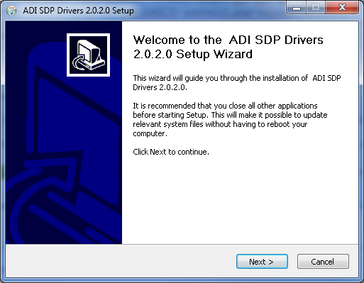
- Press “Next” to set the installation location for the SDP Drivers.
It is recommended that you install the drivers to the default directory path
C:\Program Files\Analog Devices\SDP\Drivers

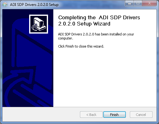
- Press “Next” to install the SDP Drivers and complete the installation of all software. Click “Finish” when done.<html><br><br></html>
Using the Evaluation Software
Software Control and Indicator Descriptions


- Connect/Reconnect Button
- When this button is pressed, the SDP-B Board makes a USB connection to the CN-0288 Board. A connection to the SDP-B Board must be made to use the software.
- Samples Numerical Control
- This numerical control determines how many samples to acquire after the Acquire Samples Button has been pressed.
NOTE: If the Enable Real-Time Checkbox is checked, this value is ignored
- Acquire Samples Button
- When this button is pressed, the SDP-B Board will collect conversion data and present the acquisitions in the chart.
- Stop Acquiring Button
- When this button is pressed, the software stop collecting data from the CN-0288 Board
- Save Data Button
- When this button is pressed, the software will save the data collected to a tab delimited ASCII spreadsheet file.
- Control Tabs
- Acquire Data - Clicking this tab brings the data collection chart to the front.
- Configure System - Clicking this tab brings the system configuration settings to the front.
- SDP Board Information - Clicking this tab brings the SDP Board revision information to the front.
- Enable Real-Time Checkbox
- When this checkbox is checked, the SDP-B will acquire samples until the Stop Acquiring Button is pressed.
- Current Temperature Numerical Indicator
- This indicator displays the current temperature measurement.
- Chart Controls
- These controls allow the user to zoom-in, zoom-out, and pan through the data collected.
- System Status String Indicator
- This indicator displays a message to the user detailing the current state of the software.
- System Status LED Indicator
- This indicator displays the current state of the software in the form of an LED. There are three status LED colors.
 Inactive
 Busy
Busy
 Error
Error
- Update Rate Radio Buttons
- This control is used to change the output word rate of the AD7790. The default value is 120 Hz and is highlighted in bold on the Configure System Tab.
- Burnout Current Radio Buttons
- When this control is enabled the 100nA current sources in the signal path are enabled.
The burnout currents can be enabled only when the buffer is active.
- Buffer Select Radio Buttons
- This control is used to set the mode of the AD7790. The default value is Unbuffered Mode and is highlighted in bold on the Configure System Tab.
- Channel Selection Radio Buttons
- This control is used to select the analog input channel of the AD7790 for conversion. The default value is AIN(+)-AIN(-) and is highlighted in bold on the Configure System Tab.
- AIN(+)-AIN(-) - Selecting this radio button allows for normal operation of the AD7790.
- AIN(-)-AIN(-) - Selecting this radio button shorts the analog input channels of the AD7790.
- Vdd Monitor - Selecting this radio button monitors the voltage applied to the Vdd pin of the AD7790. The voltage is attenuated by 5 and the resultant voltage is applied to the ∑-Δ modulator using an internal 1.17 V reference for analog to digital conversion.
- Mode Register Numerical Indicator
- This indicator displays the current contents of the Mode Register of the AD7790 ∑-Δ 16-bit ADC.
- Filter Register Numerical Indicator
- This indicator displays the current contents of the Filter Register of the AD7790 ∑-Δ 16-bit ADC.
- Reference Junction Temperature Numerical Control
- This control is used to simulate the temperature of the reference junction.
Establishing a USB Connection Link
- Follow the instructions to properly install the software and connect the hardware as described in the previous sections.
- Open the file named CN0271.exe in the installation directory.
NOTE: If the software was installed to the default location it will be found at
C:\Program Files\Analog Devices\CN0271\CN0271.exe
- Click the Connect/Reconnect Button. A window with a progress bar will load.

- Upon success, the System Status String Indicator will display SDP Board Ready to Acquire Data
Acquiring a Fixed Sample Size of Data
- Establish a USB Connection Link.
- Adjust the Samples Numerical Control to the number of samples to be acquired.
- Ensure that the Enable Real-Time Checkbox is cleared.
- Click the Acquire Samples Button
- Wait until the acquisition is complete.
Acquiring Data in Real-Time
- Establish a USB Connection Link.
- Ensure that the Enable Real-Time Checkbox is checked.
- Click the Acquire Samples Button
- Click the Stop Acquiring Button to stop the acquisition.
Saving Data to a Spreadsheet File
- Establish a USB Connection Link.
- Capture Data.
- Click the Save Data Button.
- Browse to the directory location where the spreadsheet file is to be saved.
- Name the file.
- Click the OK Button.
The software saves the spreadsheet file as ASCII text with columns separated by tabs.
resources/eval/user-guides/circuits-from-the-lab/cn0271.1368465472.txt.gz · Last modified: 13 May 2013 19:17 by James Fitzgerald