


This version is outdated by a newer approved version. This version (15 Oct 2013 09:01) is a draft.
Approvals: 0/1The Previously approved version (30 Aug 2013 23:17) is available.
This version (15 Oct 2013 09:01) is a draft.Approvals: 0/1The Previously approved version (30 Aug 2013 23:17) is available.
This is an old revision of the document!
Table of Contents
}
CN-0269 Software User Guide
Overview
CN-0269 is a high performance industrial signal level multi-channel data acquisition circuit that can process 16-channels of single-ended inputs or 8-channels of differential inputs with up to 18-bit resolution.
A single channel can be sampled at up to 1.33 MSPS with 18-bit resolution. A channel-to-channel switching rate of 250 kHz between all input channels provides 16-bit performance.
The signal processing circuit combined with a simple 4-bit up-down binary counter provides a simple and cost effective way to realize channel-to-channel switching without an FPGA, CPLD or high speed processor. The counter can be programmed to count up or count down for sequentially sampling multiple channels, or can be loaded with a fixed binary word for sampling a single channel.

Required Equipment
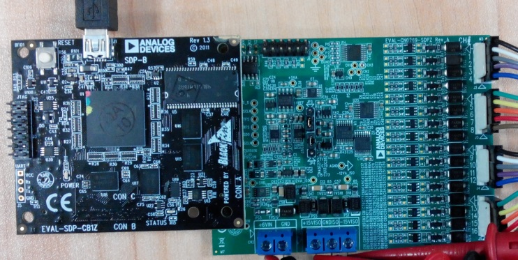
- EVAL-SDP-CB1Z Evaluation Board (SDP-B Board)
- EVAL-CN0269-SDPZ Daughter Board (CN0269 Board)
- EVAL-CFTL-6V-PWRZ Power Supply or equivalent +6V power supply
-
- (supplied with provided CD in kit)
- PC with the following Minimum Requirements
- Windows XP Service Pack 2 (32-bit)
- USB type A Port
- Processor rated at 1GHz or faster
- 512 MB RAM and 500 MB available hard disk space
- USB type A to USB type mini-B cable
- Signal Generator for Sin Wave with +/-10V Vpp and frequency upto 500KHz
General Setup
- The EVAL-CN0269-SDPZ Board connects to the EVAL-SDP-CB1Z SDP-B Board via the 120-Pin connector
- The DC Power Supply +6V Output connects to CN2 on EVAL-CN0269-SDPZ, The DC Power Supply +/-12V connects to CN1 on the EVAL-CN0269-SDPZ.

Installing the Software
- Extract the file CN0269 SDP Eval Software.zip and open the file setup.exe.
NOTE: It is recommended that you install the CN0269 SDP Evaluation Software to the default directory path C:\Program Files\Analog Devices\CN0269\ and all National Instruments products to C:\Program Files\National Instruments\
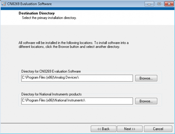
- Click Next to view the installation review page.

- Click Next to start the installation.

- Upon completion of the installation of the CN0269 SDP Eval Software, the installer for the ADI SDP Drivers will execute.
NOTE: It is recommended that you close all other applications before clicking “Next”. This will make it possible to update relevant system files without having to reboot your computer.

- Press “Next” to set the installation location for the SDP Drivers.
It is recommended that you install the drivers to the default directory path
C:\Program Files\Analog Devices\SDP\Drivers

- Press “Next” to install the SDP Drivers and complete the installation of all software. Click “Finish” when done.

Connecting the Hardware
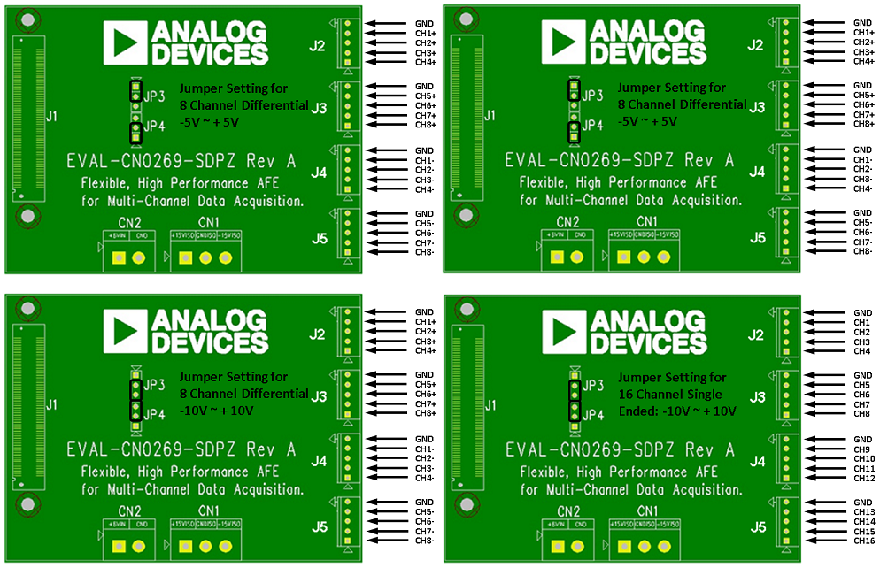
- Set the JP3 and JP4 on EVAL-CN0269-SDPZ (CN0269 Board) to select the input range and Connect the signal correctly according to the pin definition.

- Connect the USB Cable to the SDP-B Board and leave the other side of the cable unconnected.
- Connect the 6V DC power to CN2 and +/-12V DC power to CN1 and Turn on the DC power supply to power up the board.
- Connect the USB Cable to PC

Using the Evaluation Software
Software Control and Indicator Descriptions
Software Overview

- Connect Button
- When this button is pressed, the SDP-B Board makes a USB connection to the CN0272 Board. A connection to the SDP-B Board must be made to use the software.
- Start Acquisition Button
- When this button is pressed, the SDP-B Board starts to acquire data from EVAL-CN0269-SDPZ Board.
- Save Data Button
- When this button is pressed, the SDP-B Board save the data into the same directory where the application is installed.
NOTE: If the CN0269 SDP Evaluation Software is installed in the default directory, the data files could be found in C:\Program files\Analog Devices\CN0269\.
- Control Tabs
- Configuration Tab: All the configuration items through EVAL-SDP-CB1Z Board to EVAL-CN0269-SDPZ board are organized on this tab. More details about Configuration Tab will be introduced in the following Section.
- Multi-Channel Tab: This tab shows all the signals on one tab which is convenient to compare the signals from different channels. More details about Multi-Channel Tab will be introduced in the following Section.
- Single Channel Tab: This tab shows the specific channel which is more clearer than Multi-Channel Tab. More details about Single Channel Tab will be introduced in the following Section.
- SDP Information: The Firmware version of EVAL-SDP-CB1Z Board is shown on this tab. More details about SDP Information Tab will be introduced in the following Section.
- Configuration Items
- All the items that used to control EVAL-CN0269-SDPZ board.
- Hardware Configuration Diagram
- This picture block shows the way of hardware configuration in terms of jumper setting and signal connection according to the current configuration.
- System Status String Indicator
- This indicator displays a message to the user detailing the current state of the software.
- System Status LED Indicator
- This indicator displays the current state of the software in the form of an LED. There are four status LED colors.
 busy.
busy.
 error.
 inactive.
Configuration Tab
- Configuration Items
- Connector
- Signal Range
- Signal Type
- Acquisition Mode
- Scan Sequence
- Sample Rate/CH(Hz)
- Samples/CH
- Capture Mode
- Phase Compensation
Establishing a USB Connection Link
resources/eval/user-guides/circuits-from-the-lab/cn0269.1381820506.txt.gz · Last modified: 15 Oct 2013 09:01 by yue hua