


This version is outdated by a newer approved version. This version (13 Nov 2017 08:30) is a draft.
Approvals: 0/1
This version (13 Nov 2017 08:30) is a draft.Approvals: 0/1
This is an old revision of the document!
Table of Contents
CN0263 Evaluation Board Guide
Overview
CN0263 is a circuit that provides a very robust solution, with integrated overvoltage (short-to-battery [STB]) protection, for receiving CBVS video signals in harsh environments. It follows the traditional, proven architecture of isolating/separating a low voltage integrated circuit from the outside world and using an amplifier circuit for signal conditioning and protection.
ADA4830-1 is a single monolithic, high speed difference amplifier that integrates input overvoltage (short-to-battery) protection of up to 18 V with a wide input common-mode voltage range and excellent ESD robustness. It is intended for use as a receiver for differential or pseudo differential CVBS and other high speed video signals in harsh, noisy environments, such as automotive infotainment and vision systems. The ADA4830-1 combines high speed and precision, which allows for accurate reproduction of CVBS video signals, yet rejects unwanted common-mode error voltages.
ADV7180 automatically detects and converts standard analog baseband television signals compatible with worldwide NTSC, PAL, and SECAM standards into 4:2:2 component video data compatible with the 8-bit ITU-R BT.656 interface standard. The simple digital output interface connects gluelessly to a wide range of MPEG encoders, codecs, mobile video processors, and Analog Devices, Inc., digital video encoders, such as the ADV7391.
The ADV7180 and ADA4830-1 are fully automotive qualified, which makes both products ideal for infotainment and visionbased safety systems for automotive applications.
The EVAL-CN0263-EB1Z Board connects to mini-USB connector and is powered by a +7.5 V supply or +7.5 V “wall wart”.

Required Equipment
- Power Supply
- 7.5 V or 7.5 V “Wall wart”
- Triple Power Supply
- Agilent E3631A Power supply
- Video Signal Generator
- Astrodesign VG-828 Programmable Video Signal Generator
- Function generator
- Hewlett-Packard 3314A Function Generator
- A video source for signal and common-mode error voltage
- PC with the following Minimum Requirements
- Windows 7 (32-bit), Windows Vista (32-bit) or Windows XP
- USB interface
- A video display for observing the analog video output of the EVAL-CN0263-EB1Z board.
General Setup
Block assignments

- The EVAL-CN0263-EB1Z Board (CN-0263 Board) connects to the PC via USB connection
- Terminal block J1 is RCA jack for the video output
- Terminal block J2 is the +7.5 V barrel connector for wall wart supply input
- Terminal block J3 is mini DIN connector for S-video input
- Terminal block J4 RCA jack for the video input
- Terminal block J5 is the jumper for power-down mode of ADV7180
- Terminal block J6 is mini AB USB port connecting the board to PC
- Terminal block J7 is the jumper for FIELD pin of ADV7180
- Terminal block J8 is the Video Pixel Output Port of ADV7180. Has output configurations for 8-bit or 16-bit mode
- Terminal block J9 is the RCA jack for CVBS input for ADA4830-2
- Terminal block J10 is the jumper for logic high or low in the chip data address pin of serial EEPROM 24LC64
- Terminal block J11 is the jumper for power-down/disable mode of ADA4417-3
- Terminal block J12 is the jumper for output DC offset enable pin of ADA4417-3
- Terminal block J13 is the RCA jack for CVBS input to ADA4433-1, a differential video filter
- Terminal block J14 is the RCA jack for processed output CVBS signal in ADA4432-1
- Terminal block J15 is the RCA jack for positive differential output of ADA4433-1, a differential video filter
- Terminal block J16 is the RCA jack for negative differential output of ADA4433-1, a differential video filter
- Terminal block J17 is mini DIN connector for S-video output of DAC1 from ADA4433-1
- Terminal block J18 is the jumper for grounding second positive differential input of ADA4830-2
- Terminal block J19 is the jumper for grounding second negative differential input of ADA4830-2
Jumper settings
See the table in the image below for the jumper settings. Values in red are the default settings for the EVAL-CN0263-SDPZ.

Jumper 8 is for the P7 to P0 Output/Input Pin Mapping of ADV7180. Table below summarizes the output/input mapping depending on chosen format and mode of operation.

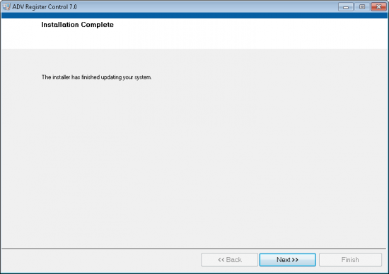
Installing the Evaluation Software
- Extract the file CN0263_Evaluation_Software.zip and open the file setup.bat.
NOTE: It is recommended that you install the software to the default directory path C:\Program Files (x86)\Analog Devices\ADV Register Control 7.0\ and all National Instruments products to C:\Program Files\National Instruments\

- Click Next to view the installation review page

- Click Next to start the installation
Using the Evaluation Software
Main Tab

More Information and Useful Links
Schematic, PCB Layout, Bill of Materials
EVAL-CN0263-SDPZ Design & Integration Files
- Schematics
- PCB Layout
- Bill of Materials
- PADS project
End of Document
resources/eval/user-guides/circuits-from-the-lab/cn0263.1510558211.txt.gz · Last modified: 13 Nov 2017 08:30 by Trisha Cabildo