


This version is outdated by a newer approved version. This version (15 Sep 2017 20:45) is a draft.
Approvals: 0/1
This version (15 Sep 2017 20:45) is a draft.Approvals: 0/1
This is an old revision of the document!
Table of Contents
EVAL-CN0190-EB1Z Overview
CN0190 is a reference solution for multivoltage power systems. The design can easily be adapted to customer requirements and provides the most popular system voltages. The circuit uses an optimum combination of switching and linear regulators to provide an overall efficiency of approximately 78% when the outputs are fully loaded. Output power delivered under full load is approximately 25 W.
The circuit supplies most of the typical power rails required for digital and analog circuits and also demonstrates an easy way to realize overvoltage, undervoltage, and overcurrent detection and protection. In addition, this module shows how to implement sequencing and power margining control.
The circuit is flexible and can accept a wide input voltage range from 6 V to 14 V. This is possible because the highly efficient switching controllers and regulators used in the first stage of each power rail have correspondingly wide input ranges. The ADM1178 block provides overvoltage and overcurrent detection and protection for the input supply, as well as hotswap control for the whole system. The ADM1066 offers a single-chip solution for power supply monitoring and sequencing control for all of the 12 power rails and also margining control for the 3.3V(2A) rail.

Equipment Needed (Equivalents Can be Substituted)
- Tektronix TDS3034B 4-channel 300 MHz color digital phosphor oscilloscope
- Tektronix P6139A, 500 MHz, 8 pF, 10 MΩ, 10× passive prob
- Agilent N3302A, 150 W, 0 A to 30 A, 0 V to 60 V electronic load module combined with N3300A
- Agilent E3631A, 0 V to 6 V, 5 A; 0 V to ±25 V, 1 A, triple output dc power supply
- Agilent 3458A, 8.5 digit digital multimeter
- Fluke 15B digital multimeter
- USB-SDP-CABLEZ
- PC (Windows 2000 or Windows XP) with USB interface
Test Setup Functional Block Diagram
Power Rails Efficiency Measurements

Efficiency = POUT/PIN = (VOUT × IOUT) ÷ (VIN × IIN)
- POUT can be calculated by multiplying VOUT by IOUT
- VIN and IIN can be read directly from the display window of the Agilent E3631A dc power supply
- Electronic load should be set to constant current mode
- POUT can be calculated by multiplying VOUT by IOUT
- VIN and IIN can be read directly from the display window of the Agilent E3631A dc power supply
- Electronic load should be set to constant current mode
Ripple and Transient Response Measurements

- Channel A of the oscilloscope monitors the
output voltage of the module
- Channel B monitors the voltage across the 0.1 Ω current sense resistor, which is proportional to the load current
- Electronic load should be set to “switch” mode with preset amplitude and frequency
- Channel B monitors the voltage across the 0.1 Ω current sense resistor, which is proportional to the load current
- Electronic load should be set to “switch” mode with preset amplitude and frequency
Connectors and Jumper Configurations

Input Power
Connector 1, and should be between +6V and +14V
Output Power Options
| Image Indicator | Voltage Output | Current Output | Power Topology |
|---|---|---|---|
| Connector 2 | +3.3V | 2A | Synchronous Buck |
| Connector 3 | +1.8V | 1A | Synchronous Buck |
| Connector 4 | +1.5V | 1A | Synchronous Buck |
| Connector 5 | +1.0V | 2A | LDO |
| Connector 6 | +1.2V | 0.5A | Synchronous Buck |
| Connector 7 | +3.0V | 0.1A | LDO |
| Connector 8 | -5.0V | 0.2A | Inverted Buck/Boost |
| Connector 9 | +5.0V | 1A | Synchronous Buck |
| Connector 10 | +2.5V | 1A | Synchronous Buck |
| Connector 11 | +3.3V | 0.1A | LDO |
| Connector 12 | +2.5V, +5V, +12V, +15 | 0.1A | Sepic-Cuk |
| Connector 13 | -2.5V, -5V, -12V, -15 | 0.1A | Sepic-Cuk |
- To select the Voltage outputs on Connector 12 and Connector 13, you must setup the switch matrix. Use the following table to select those outputs:

I2C Programming Interface
I2C serial interface is on Connector 15 (1- SCLK, 2 - SDA, 3 - GND)
You can design your own control strategy and download it into the
ADM1066 through this I2C bus connector JP1 to make the power
monitoring and sequencing control for your own application
using the ADM106x Super Sequencer Evaluation Board Software and follow instructions below
Software and Driver Installation
Driver Installation
Download the USB-SDP-CABLEZ driver.
- Install the USB-SDP-CABLEZ driver
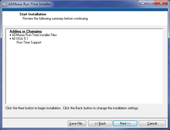
- Open the file setup.exe located at the path \ADMxxxx Run-Time Installer\Installer\Volume\setup.exe

It is recommended that you install the software to the default directory.
- Follow the on-screen prompts to install the software
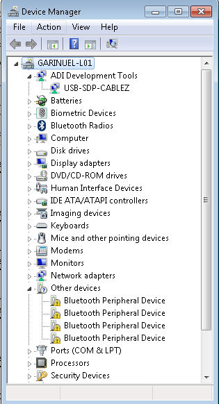
- Plug in the USB-SDP-CABLEZ into your PC or labtop using the USB cable.
- Windows will automatically find the new hardware(USB-SDP-CABLEZ) plugged the into the PC.


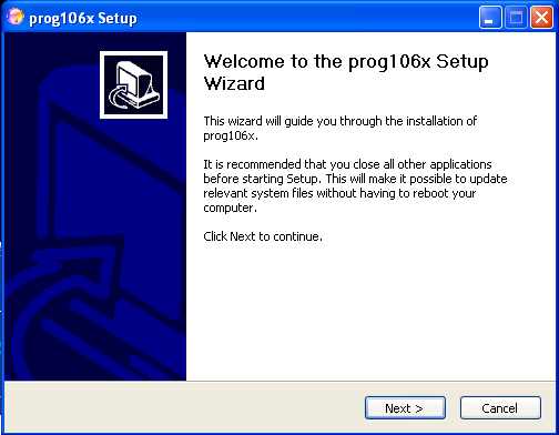
Sequencer Software Installation
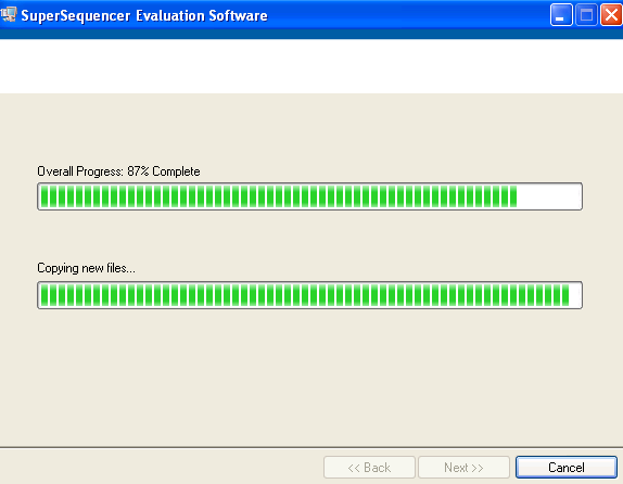
Download and Install the SuperSequencer Application Software.
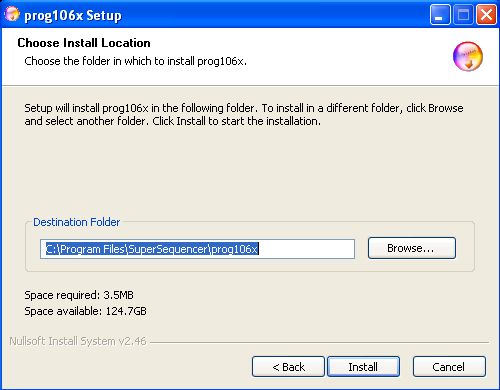
- Open the file setup.exe located at the path \SuperSequencer Apps SW Installer\Volume\setup.exe

It is recommended that you install the SuperSequencer Evaluation Software to the default directory path C:\Program Files\
- Follow the on-screen prompts to install the software.


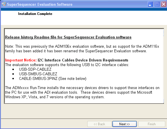
- Install Graphviz.

- Upon completion, follow the on-screen promps to install the prog106x Setup Application Software


Visit Super Sequencer User Guide and Software Programming Tool to know more about the Application Software and Graphviz User Guide for automatic generation of state diagrams for ADM1066
Downloading Firmware for ADM1066
- Copy the eeprom file i.e. ADM1066_SuperSequencing_REVB.hex in the root directory on Disk C: (i.e. C:\ADM1066_SuperSequencing_REVB.hex)
- Plug USB to I2C converter dongle into the USB port on your PC. Plug the other side of the cable into the JP1 on the right side of the EVAL-CN0190-EB1Z.
Make sure the marks for the signals of JP1 on the PCB match the marks on the USB-SDP-CABLEZ.
Signal Connection:
SCL↔SCL
SDA↔SDA
GND ↔GND
Signal Connection:
SCL↔SCL
SDA↔SDA
GND ↔GND
- Turn on the power to the supply of EVAL-CN0190-EB1Z
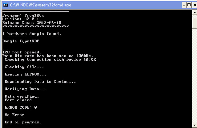
- Open the Command Prompt (C:\Windows\System32\cmd.exe)

- In the cmd.exe, key the command prog106x download 6A c:\ADM1066_SuperSequencing_REVB.hex and Press Enter
ADM1066_SuperSequencing_REVB.hex file name might be different, depends on the user
- The on-chip EEPROM of ADM1066 is successfully programmed if the picture below is shown on the screen after several seconds.
- Turn off and on the power to the supply In order to make ADM1066 update the program from embedded EEPROM.


Schematic, PCB Layout, Bill of Materials
EVAL-CN0190-EBZ Design & Integration Files
- Schematics
- PCB Layout
- Bill of Materials
- PADS project
resources/eval/user-guides/circuits-from-the-lab/cn0190.1505501125.txt.gz · Last modified: 15 Sep 2017 20:45 by Brandon Bushey