


The most recent version of this page is a draft. This version is outdated by a newer approved version.This version (21 Dec 2017 03:21) was approved by Trisha Cabildo.
This version is outdated by a newer approved version.This version (21 Dec 2017 03:21) was approved by Trisha Cabildo.This is an old revision of the document!
Table of Contents
CN0178 Evaluation Board Guide
Overview
CN0178 is a circuit that measures the rms signal strength of RF signals with varying crest factors (peak-to-average ratio) over a dynamic range of approximately 65 dB and operates at frequencies from 50 MHz up to 9 GHz using the ADL5902 TruPwr™ detector. The measurement result is provided as serial data at the output of a 12-bit ADC. A simple 4-point system calibration at ambient temperature is performed in the digital domain.
The ADL5902 provides a solution in a variety of high frequency systems requiring an accurate measurement of signal power. It can operate from 50 MHz to 9 GHz and can accept inputs from −62 dBm to at least +3 dBm with large crest factors, such as GSM, CDMA, W-CDMA, TD-SCDMA, WiMAX, and LTE modulated signals.
The AD7466 12-bit, high speed, low power, successive approximation analog-to-digital converters (ADC). It operates from a single 1.6 V to 3.6 V power supply and feature throughput rates up to 200 kSPS with low power dissipation. The parts contain a low noise, wide bandwidth track-and-hold amplifier, which can handle input frequencies in excess of 3 MHz.
The EVAL-CN0178-SDPZ board connects to ADI’s System Demonstration Platform (SDP) and is powered by a +6 V supply or +6 V “wall wart”.

Required Equipment
- EVAL-SDP-CB1Z Controller Board (SDP-B Board)
- 6 V or 6 V Wall wart
- Agilent E3631A power supply
- PC with the following Minimum Requirements
- Windows 7 (32-bit), Windows Vista (32-bit) or Windows XP
- USB interface
- RF signal source
- Rohde & Schwarz SMT-03 RF signal source
- Coaxial RF cable with SMA connectors
General Setup
Block assignments

- The EVAL-CN0178-SDPZ (CN-0178 Board) connects to the EVAL-SDP-CB1Z (SDP-B Board) via the 120-Pin connector
- The EVAL-SDP-CB1Z (SDP-B Board) connects to the PC via the USB cable.
- Terminal block J1 is the +6 V power supply
- Terminal block J2 is the +6 V barrel connector for wall wart supply input
- Terminal block J3 is the SMA connector for RF input
Test setup

- Connect the 120-pin connector on the EVAL-CN0178-SDPZ Evaluation Board to the connector marked “CON A” on the EVAL-SDP-CB1Z evaluation (SDP) board
- Connect the RF signal source to the EVAL-CN0178-SDPZ Evaluation Board via the SMA RF input connector
- With power to the supply off, connect a +6 V power supply to the pins marked “+6V” and “GND” on the board
- If available, a +6 V “wall wart” can be connected to the barrel connector on the board and used in place of the +6 V power supply
- Connect the USB cable supplied with the SDP board to the USB port on the PC
- Apply power to the +6 V supply (or “wall wart”) connected to EVAL-CN0178-SDPZ Evaluation Board
- Launch the evaluation software
- Connect the USB cable from the PC to the USB mini connector on the SDP board
Do not connect the USB cable to the Mini-USB connector on the SDP board before turning on the dc power supply for the EVAL-CN0178-SDPZ.
Calibration
Because the slope and intercept of the system vary from device to device, a system level calibration is required. For this board, a 4-point calibration is used to correct for some non-linearity in the RF detector's transfer function particularly at the low end.
- Apply four known signal levels to ADL5902. Note that it should be well within the linear operating range of the device

- Measure the corresponding output codes from the ADC
- Calculate SLOPE_ADC and INTERCEPT calibration coefficients using the following equations:
- SLOPE_1 = (CODE_1 - CODE_2)/(PIN_1 - PIN_2)
- INTERCEPT1 = CODE_1/(SLOPE_ADC/PIN_1)
- This calculation is repeated using CODE2/CODE3 and CODE3/CODE4 to calculate SLOPE2/INTERCEPT2 and SLOPE3/INTERCEPT3 respectively
- These will be used to calculate the unknown input power level, PIN, when operation in the field using the equation
- PIN = (CODE/SLOPE) + INTERCEPT
- The observed code from the ADC will be compared to the calibration coefficient codes in order to retrieve the appropriate SLOPE and INTERCEPT calibration coefficients.
- Example: If CODE from ADC is between CODE1 and CODE2, then SLOPE1/INTERCEPT1 should be used

Installing the Evaluation Software
- Extract the file CN0178_Evaluation_Software.zip and open the file setup.exe.
NOTE: It is recommended that you install the CN0178 Evaluation Software to the default directory path C:\Program Files (x86)\Analog Devices\CN0178\ and all National Instruments products to C:\Program Files\National Instruments\

- Click Next to view the installation review page
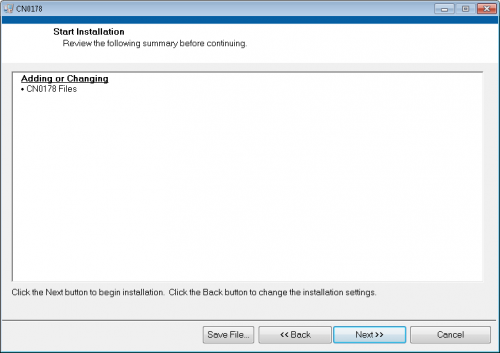
- Click Next to start the installation

- Upon completion of the installation of the CN-0178 Evaluation Software, the installer for the ADI SDP Drivers will execute.
NOTE: It is recommended that you close all other applications before clicking “Next”. This will make it possible to update relevant system files without having to reboot your computer.

- Press “Next” to set the installation location for the SDP Drivers.
It is recommended that you install the drivers to the default directory path
C:\Program Files\Analog Devices\SDP\Drivers

- Press “Install” to install the SDP Drivers and complete the installation of all software. Click “Finish” when done.

Using the Evaluation Software
Main Window

- Connect Button - Starts the connection between the CN0178 Evaluation Board and SDP-B Controller Board.
- Disconnect Button - Ends the connection between the CN0178 Evaluation Board and SDP-B Controller Board
- SDP Connector - Selects which 120-pin connection of the SDP-B Board to use
- Input Power - Indicate input signal power level
- Frequency - Indicate input signal frequency
- Data Acquisition Controls

- Sample Data - Start acquisition of measurement data
- Remove Data Point - Remove a data point from samples
- Clear Data - Clear the current measurement data
- Save Data - Save measurement data to file
- Sample Data Graph Tab - Shows the XY plot of ADC code and output error (%) with respect to the shunt voltage

- Plot Options - Edit plot display and options like interpolation and color of output waveform
- Calibration Tab
- Calibration Inputs - Four point input power levels used for calibration purposes
- Calibration Data - Enable calibration of the device
- Calibration Coefficients - Read only. Calculated calibration coefficients based on four point input power levels
- Administration Tab

- Read Firmware - Reads the firmware of CN0150 Evaluation Board
- Flash LED - Flashes the LED on the SDP controller board
- Quit Button - Closes the evaluation software

Running the System
- Open the CN0178.exe application from the default installation location
- Set the correct connector and click the Connect Button
- Upon successful connection, calibrate the device through the calibration tab
- After proper calibration, set the correct input parameters and control the data measurement through the data acquisition control buttons
- Click Disconnect if finished
- Click Quit to exit the program
More Information and Useful Links
Schematic, PCB Layout, Bill of Materials
EVAL-CN0178-SDPZ Design & Integration Files
- Schematics
- PCB Layout
- Bill of Materials
- PADS project
End of Document
resources/eval/user-guides/circuits-from-the-lab/cn0178.1512380339.txt.gz · Last modified: 04 Dec 2017 10:38 by Trisha Cabildo