


The most recent version of this page is a draft. This version (04 Apr 2019 15:04) was approved by Istvan Csomortani.The Previously approved version (04 Apr 2019 15:00) is available.
This version (04 Apr 2019 15:04) was approved by Istvan Csomortani.The Previously approved version (04 Apr 2019 15:00) is available.This is an old revision of the document!
Table of Contents
ADuM7701 - Reference Design
Supported Devices
Supported Carrier Board
Overview
The ADuM7701 is a high performance, second-order, Σ-Δ modulator that converts an analog input signal into a high speed, single-bit data stream, with on-chip digital isolation based on Analog Devices, Inc., iCoupler® technology. The device operates from a 4.5 V to 5.5 V power supply range (VDD1) and accepts a pseudo differential input signal of ±250 mV (±320 mV full-scale). The pseudo differential input is ideally suited to shunt voltage monitoring in high voltage applications where galvanic isolation is required.
The analog input is continuously sampled by a high performance analog modulator and converted to a ones density digital output stream with a data rate of up to 21 MHz. The original information can be reconstructed with an appropriate sinc3 digital filter to achieve an 86 dB signal-to-noise ratio (SNR) at 78.1 kSPS with a 256 decimation rate and a 20 MHz master clock. The serial input and output operates from a 5 V or a 3 V supply (VDD2).
The serial interface is digitally isolated. High speed complementary metal-oxide semiconductor (CMOS) technology, combined with monolithic transformer technology, results in the on-chip isolation providing outstanding performance characteristics, superior to alternatives such as optocoupler devices. The ADuM7701 device is available in both a 16-lead and an 8-lead wide-body SOIC and has an operating temperature range of −40°C to +125°C.
Applications
- Shunt current monitoring
- AC motor controls
- Power and solar inverters
- Wind turbine inverters
- Analog-to-digital and optoisolator replacements
HDL Reference Design
The provided HDL reference design support's both the ADuM7701 and AD7405 devices. One of the main difference between thees two devices is the type of the digital data lines. In case of ADuM7701 it is a single ended lines, and in case of the AD7405 is differential.
User can configure the corresponding interface type, by setting the adc_port_type Tcl variable in the system_project.tcl file. Note that this variable should be set before generating any bit file.
The output of the device is a continuous digital bit stream, to reconstruct the original input signal information, this output bit stream needs to be digitally filtered and decimated. A simple sinc filter is recommended to reconstruct the original input signal information received from the ADuM7701. The following equation describes the transfer function of the sinc filter:
where DR is the decimation rate and N is the sinc filter order. The implemented filter is a 3rd order sinc filter.
The output of the filter is connected to a DMA, which will handle the data transfer into the system memory. See the data path in block diagram bellow:

The external clock rate (MCLKIN) can be set in the system_bd.tcl file, by changing the value of the ext_clk_rate variable.
Create the project with SDK
- Open Xilinx Software Development Kit (XSDK) and provide the workspace location.
- Create a new Application Project: go to File → New → Application Project

- Create a new Hardware Platform: click New from the Target Hardware section

- Specify the already generated Hardware Platform Specification File (more details about the generation: https://wiki.analog.com/resources/fpga/docs/build): in the Target Hardware Specification section browse the desired file

- Give a name to the project and to the board support package and click Next

- Select the Empty Application templeta and click Finish

- The new Empty Application project should look like:

Some applications (e.g. FMCOMMSx), when a Microblaze processor is used, requires an increased HEAP size for dynamic memory allocation. Make sure the HEAP size is at least 0x100000. 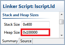

- Copy the source code files into the src directory
- Make sure you uncomment the the required carrier vendor and CPU architecture from the app_config.h (or config.h) header file.
- Example for choosing the Altera carrier in the app_config.h header file:
//#define XILINX
#define ALTERA
- If there are multiple folders present in in the src one, include all the paths of the folders: go to the settings of the project and in the C/C++ Build → Settings → Tool Settings → gcc compiler → Directories section and add the paths of all the folders.
- The SDK should automatically build the projects and the Console window will display the result of the build. If the build is not done automatically select the Project → Build Automatically menu option.
- At this point the software project setup is complete, the FPGA can be programmed and the software can be downloaded into the system. You can program the FPGA by clicking on Xilinx Tools → Program FPGA
- After the FPGA was programmed, we need to create a new Run configuration, by selecting Run → Run Configurations…, in the Run Configuration windows select the Xilinx C/C++ application (System Debugger) and click at the New Configuration button at the upper left corner.

- If your target carrier has a Zync SoC, make sure, that you specify the Initialization file, and select the Run ps7_init and Run ps7_post_config options.

- At the Application tab define your current project name and application executable. (.elf)

- The output of the example program can be viewed in the SDK console by enabling the Connect STDIO Console option and setting the baud rate of the UART port to 115200.

- As an alternative a UART terminal can be used to capture the output of the example program. The number of used UART port depends on the computer's configuration. The following settings must be used in the UART terminal:
- Baud Rate: 115200bps
- Data: 8 bit
- Parity: None
- Stop bits: 1 bit
- Flow Control: none
- When the run configuration is done, the software can be started by clicking the Run button.
- Your new bare metal application should run
Driver Description
Functions Declarations
| Function | Description |
|---|---|
int32_t adum7701_init(adum7701_dev **dev, adum7701_init_param init_param); | Initialize the device. |
int32_t adum7701_remove(adum7701_dev *dev); | Free the resources allocated by adum7701_init(). |
Types Declarations
typedef struct { /* GPIO */ gpio_desc *dec_ratio; gpio_desc *filter_reset; } adum7701_dev; typedef struct { /* GPIO */ gpio_init_param dec_ratio; gpio_init_param filter_reset; } adum7701_init_param; |
Downloads
/srv/wiki.analog.com/data/pages/resources/eval/user-guides/adum770x.txt · Last modified: 20 Jan 2022 16:25 by z zg