ADMV96S-WGBE-EK1 User Guide
Introduction
The ADMV96S-WGBE-EK1 is a complete evaluation and prototyping system for 60 GHz short data links. It consists of a pair of receiver and transmitter boards with a 1 Gbps Ethernet interface on each side of the wireless link.
The 60 GHz wireless link is implemented by the ADMV9615 and ADMV9525 modules. These are coupled with a SerDes device which translates the modules’ SGMII interface to RGMII so that it can be connected to an ADIN1300 industrial low latency and low power 1 Gbps Ethernet PHY. This enables each side of the wireless link to act as an Ethernet port and essentially create a seamless wire-like connection between two ends of an Ethernet cable.
The on-board MAX32650 ultralow power ARM® Cortex®-M4 microcontroller controls the system’s operation and implements the algorithms to configure the wireless link in real time so that optimal link quality is constantly maintained over temperature and various operating conditions. An open-source software stack is provided for firmware development as well as reference applications. The MAX32650 can be programmed and debugged through a JTAG SWD header which can also be used for connecting the Wethlink GUI application to the board.


Features
Applications
Slip rings
Magnetic resonance imaging systems
Autonomous Guided Vehicles
Truck and trailer coupling
Railway coupling
Specifications
| User Interfaces |
| LEDs | Power status, TX and RX gain status, TX and RX PLL lock status, Ethernet status |
| Connectivity |
| 10-pin Cortex SWD header | May be used with MAXDAP (MAX32625PICO) external adapter for connecting the Wethlink GUI to the evaluation board and for programming firmware. |
| Ethernet | 1xRJ45 1 Gbps / 100 Mbps / 10 Mbps Ethernet port |
| Power supply |
| External power | 12 VDC at 2A, 2.10 mm ID (0.083“), 5.50 mm OD (0.217”) connector |
| Mechanical Specs |
| Dimensions | 3.283 x 2.362 |
Package Contents
Getting your system up and running
Access hardware setup procedure, design files, and software installer through these pages:
Application Development
ADMV9615 and ADMV9625 Contactless Ethernet Link Labeled Pair1 and Pair-2

Hardware Connections

Mount the ADMV9615 and ADMV9625 Assemblies onto the guide rails with patch antennas facing each other.
Connect 12
V power supplies.
Connect one RJ45 Ethernet connector to your PC.
Connect the other RJ45 Ethernet connector to your Local Area Network.
Turn off your PC's Wi-Fi connection.
Within a few seconds, your PC should connect to your
LAN with a speed of up to 1
Gbps (if your network can support it)
(Optional) Connect MAXDAP connector using a micro-
USB to your PCs if you would like to configure the firmware.
ADMV9615 and ADMV9625 Contactless Ethernet Link Labeled Pair-1 and Pair-2

Hardware Connections

Mount the ADMV9615 and ADMV9625 assemblies onto the guide rails with patch antennas facing each other.
Connect 12
V power supply, 2 PL.
Connect one RJ45 Ethernet connector to PC1’s Ethernet jack.
Connect the other RJ45 Ethernet connector to PC2’s Ethernet jack.
File Sharing Setup
The following procedure was taken from: How to Share Files between Two Computers Using LAN Cable – TechWiser
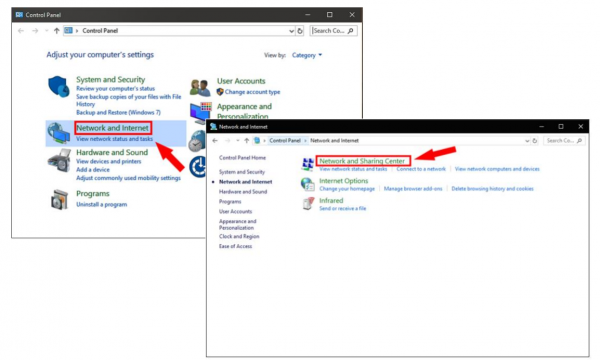
On PC1, go to the Start menu and search “Control Panel”. Once you see it, click on it, to open it. 
Choose Networks and Internet.
Next, choose Network and Sharing Center.
Click on Advanced Sharing Settings.
Choose
All Networks.


Choose
Turn on Sharing.

Turn off Password Protection (Once Done with File Sharing Turn Password Protection Back On)
Perform steps 2 through 6 for PC2.
To put both PCs on the same network, manually set up IP settings by opening Control Panel.
Choose Network and Sharing.
Select Ethernet and click Properties.
Select Internet Protocol Version 4 (TCP/IPv4).
Select Properties.
For PC1, choose “Use the following IP address” 
Use the following DNS server address:
Preferred
DNS Server:
208.67.222.222 Alternate
DNS server:
208.67.220.220
For PC2, choose “Use the following IP address” 
Use the following DNS server address:
Preferred
DNS Server:
208.67.222.222 Alternate
DNS server:
208.67.220.220

Now open windows explorer and click on the Network Tab.
If everything is set up properly both computers should appear.
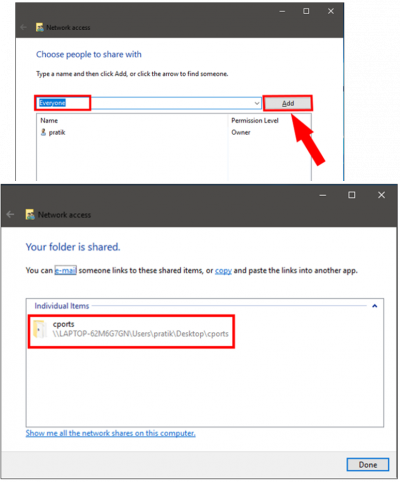
But you still must share a target Folder on
LAN.
Create a new Folder on the Desktop and put some large files into it.


Once Shared, the next window shows the location of the folder
That’s it. Go back to the PC from where you want to access the file, open the Networks panel and click on the other computer’s name.
Here you will see the folder you just shared. Just open the folder and transfer files and folders as you normally do. Copy and paste, etc.
You can repeat the steps from the other computer as well.

Example 3 – Use Iperf to Check Ethernet Link Speed
ADMV9615 and ADMV9625 Contactless Ethernet Link Labeled Pair1 and Pair2

Hardware Connections

Mount the ADMV9615 and ADMV9625 assemblies onto the guide rails with patch antennas facing each other.
Connect 12
V power supplies.
Connect one RJ45 Ethernet connector to PC1’s Ethernet jack.
Connect the other RJ45 Ethernet connector to PC2’s Ethernet jack.
Iperf
Follow the Procedure from Example 2 for File Sharing Using a 2 PC LAN:
Iperf is a free tool for network performance and measurement, download it here

Unzip the downloaded archive.
On PC1, open a DOS Command window and navigate to the directory where iperf is installed. Type in
cd C:\Users\Public\Documents\iperf-3.1.3-win64
“iperf3.exe –s”
“cd C:\Users\Public\Documents\iperf-3.1.3-win64”
“iperf3.exe -c 192.168.1.1”

Iperf tests the link speed about 950
Mbps.
Resources
Help and Support
For questions and more information please contact us on the Analog Devices Engineer Zone.


