


This version (05 Apr 2024 03:32) was approved by Joyce Velasco.The Previously approved version (05 Apr 2024 02:53) is available.
Table of Contents
AD-MAX32SXWISE-SL: Long Range Wireless Radio Development Kit based on MAX32670 MCU and SX1261 RF Transceiver
Overview
The AD-MAX32SXWISE-SL development kit is a tool intended for designing solutions based on low-power, long range proprietary radio communication technique. This platform features the SX1261 RF transceiver based on spread spectrum modulation techniques derived from chirp spread spectrum (CSS) technology, and supports a frequency range from 800 MHz to 960 MHz. This solution is also based on the MAX32670 ultralow power microcontroller based on Arm Cortex-M4 processor.
The kit is composed of a development board and equipped with sensor modules, providing users with a complete system that is suitable for quick prototyping and development of IoT applications. The design includes a gateway, which is crucial for establishing connectivity between the LPWAN devices and the backend or application server. This component is vital for data transfer and communication.
This also comes with software that allows users to observe nodes in a graphical user interface (GUI) dashboard. This feature enhances the monitoring and management capabilities of the system. To use the development board, users need to flash it with functional firmware. A simple join example has been open-sourced, providing more flexibility and easy customization in terms of firmware development.
Overall, the AD-MAX32SXWISE-SL development kit offers a comprehensive and user-friendly solution for individuals or developers interested in exploring and implementing LPWAN technology for IoT applications.
Features
- Provides the user with a platform to evaluate the features and performance of the evaluation kit.
- Allows the user to prototype and test their IoT applications before moving on to full-scale development.
- Provides tools for analyzing the power consumption of the device, helping the user to optimize their applications for energy efficiency.
- Includes development tools, libraries, and documentation to assist user in writing and debugging their code.
- Helps the user analyze and study the different modulation schemes, data rates, and other parameters relevant to IoT communication.
- Comes with user-friendly interfaces, documentation, and software tools that simplify the integration process which can save developers time and effort when incorporating the SX1261 into their IoT devices.
Applications
- Battery-Powered Medical Devices
- Industrial Sensors
- Optical Communication Modules
- Secure Radio Modem Controller
- Smart Sensor Controller
- System Housekeeping Controller

System Architecture

Specifications
| MCU |
|---|
| Arm Cortex-M4 Core with FPU up to 100 MHz |
| 384 kB Flash Memory with error correction |
| 160 kB SRAM (128 KB with ECC enabled), optionally preserved in lowest power modes |
| Security |
| Available secure boot |
| Support cryptographic algorithms, including AES-128/192/256, 1024-bit DSA, 2048-bit (CRT) and secure boot loader |
| Power |
| Ultralow power Real Time Clock with integrated power switch |
| Average battery life: more than 10 years |
| Long Range Radio |
| Support FSK, GFSK, MSK, GMSK, and Long Range FHSS modulations |
| Programmable bit rate up to 62.5 kbps and 300 kbps |
| Support of all major sub-GHz ISM bands from 150 MHz to 960 MHz |
| High sensitivity: down to -148 dBm |
| Transmission distance: up to 15 km |
Components
When you purchase the AD-MAX32SXWISE-SL development kit, the package comes with the following boards and accessories:
- Base Board:
- MAX32670-SX-ARDZ Base board
- Component Sensor Nodes:
- EV-STRUCTURAL-ARDZ for Structural Monitoring
- EV-FLOWMETER-ARDZ for Flow Rate Metering
- EV-ADE9000SHIELDZ for Electric Metering
- Gateway Concentrator
- RAK5146 PiHAT Kit
- Raspberry Pi 4 Model B with Power Supply Adapter
- MAX32625PICO Programming Adapter
- Micro SD Card
- LAN Cable
What is a Base Board?
A Base Board contains an RF transceiver chip and a microcontroller, which combine all the required elements for long range communication. This platform uses the chirp spread spectrum technique, allowing sensors to connect to a network and send and receive data in long distances.
MAX32670-SX-ARDZ Base Board
This development kit comes with the MAX32670-SX-ARDZ as its base board. This board is consisting of the MAX32670 high-reliability, ultralow power microcontroller based on Arm Cortex-M4 processor, and the SX1261 long range transceiver module.

What are Sensor Nodes?
Sensor nodes are devices that wirelessly send or receive messages to and back from the gateways. These devices communicate with nearby gateways connected through a network server. Depending on the intended applications, sensors can transmit various type of data such as temperature, flow rate, vibration, etc.
Below are the sensor nodes compatible with the MAX32670-SX-ARDZ Base Board. All of these 3 sensors are included in the AD-MAX32SXWISE-SL development kit.
EV-STRUCTURAL-ARDZ Sensor for Structural Monitoring
The EV-STRUCTURAL-ARDZ is a vibration sensor that uses the ADXL343 digital output MEMS accelerometer chip and the ADIS16203 programmable 360° inclinometer. Aside from providing vibration data, this end node also features the MAX30210 digital temperature sensor which gives the option to shut down sensitive machines and equipment for smart motor sensing applications. This vibration sensor can also detect if the horizontal position of the sensor changes, which points towards a collapse of the structure where the sensor was deployed.

EV-FLOWMETER-ARDZ Sensor for Flow Rate Metering
The EV-FLOWMETER-ARDZ is an ultrasonic time-of-flight (ToF) flow meter that sends and receives ultrasound waves between piezoelectric transducers in both the upstream and downstream directions in the pipe. By measuring the TOF difference between the upstream and downstream wave travels, utilizing sophisticated digital signal processing techniques, a very accurate flow rate can be calculated.

EV-ADE9000SHIELDZ Sensor for Electric Metering
The EV-ADE9000SHIELDZ is an Arduino shield compatible with Arduino Zero. The shield can be directly interfaced with current transformers and voltage leads. It enables quick evaluation and prototyping of energy and power quality measurement systems with the ADE9000. Arduino library and application examples are provided to simplify implementation of larger systems.

System Setup
PHASE 1: Hardware Setup
Note that this setup only applies for MAX32670-SX-ARDZ Base Board. Users may use a different base board or microcontroller, however the firmware built for this demo application cannot be used as this is specifically designed for the MAX32670-SX-ARDZ.
Equipment Needed
- One (1) MAX32670-SX-ARDZ Base Board
- One (1) MAX32625PICO Rapid Development Platform with 10-pin ribbon cable
- with firmware image: MAX32625PICO Firmware Image for MAX32670
- One (1) CR123A Battery or any equivalent external DC power supply (+3 V to +4.7 V)
- Note that this is not included in the kit
- One (1) Micro USB to USB cable
- Host PC (Windows 10 or later)

- Insert one CR123A battery (3 V to 4.7 V) into the battery holder (BT1 connector) of the MAX32670-SX-ARDZ Base Board.
Make sure to check for the battery polarity in the BT1 connector, refer to the figure below. The DS3 LED will light up indicating that you have inserted the battery correctly and that power is provided in the base board.

- Connect one Sensor Node to the MAX32670-SX-ARDZ Base Board by aligning the corresponding Arduino headers on each board.
You do not have to set up the three sensor nodes altogether, just choose one from the available sensors in the kit:
- EV-STRUCTURAL-ARDZ for Structural Monitoring
- EV-FLOWMETER-ARDZ for Flow Rate Metering
- EV-ADE9000SHIELDZ for Electric Metering
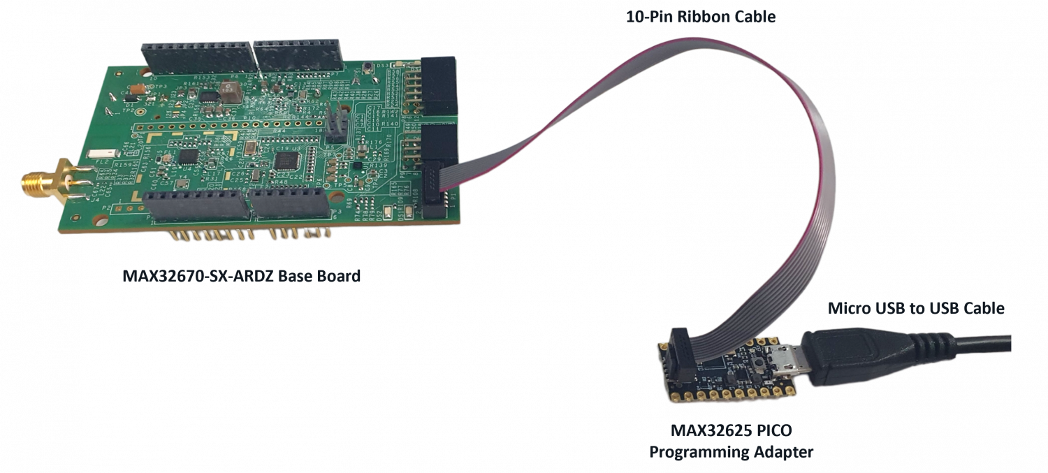
- Connect the MAX32625PICO programming adapter to the MAX32670-SX-ARDZ Base Board through the 10-pin ribbon cable.
Make sure that the MAX32625PICO programming adapter has been flashed with the correct image before connecting it to the MAX32670-SX-ARDZ Base Board. If you do not know how to load the image, click on the instructions below:
- Connect the MAX32625PICO programming adapter to the Host PC using the micro USB to USB cable.


Once you have completed this setup, proceed to PHASE 2 found in ADI Long Range Wireless Radio Software User Guide.
Resources
Design and Integration Files
AD-MAX32SXWISE-SL Design Support Package
- Schematic
- Bill of Materials
- Layout
- Fabrication Files
Help and Support
For questions and more information about this product, connect with us through the Analog Devices Engineer Zone.
resources/eval/user-guides/ad-max32sxwise-sl.txt · Last modified: 05 Apr 2024 03:32 by Joyce Velasco