


This version (01 Apr 2016 16:31) was approved by Dragos Bogdan.The Previously approved version (18 Mar 2016 16:55) is available.
Table of Contents
AD9361 No-OS Setup
Generic Platform
The AD9361 No-OS Software together with the Generic Platform Driver can be used as a base for any microprocessor platform.
The Platform Driver implements the communication with the device and hides the actual details of the communication protocol to the AD9361 driver. When the desired type of processor is chosen, the specific communication functions have to be implemented.
Code Size Information
The following information was obtained compiling the AD9361 project (with the Generic Platform Driver integrated) using the gcc v4.7.2 and the Optimize for size (-Os) option enabled.
 text	   data	    bss	    dec	    hex	filename
45159	   1624	     24	  46807	   b6d7	ad9361_generic
Note: The source code from the GitHub SHA 13c1ba56164f4b63844f63e5dd596286b6faf8b3 was used for calculating the code size information (https://github.com/analogdevicesinc/no-OS/tree/13c1ba56164f4b63844f63e5dd596286b6faf8b3/ad9361/sw).
Xilinx Platform
This guide provides some quick instructions on how to setup the AD-FMCOMMS2-EBZ on either:
The ML605 XPS project remain on this website only for legacy purposes. The support for XPS projects has been discontinued.
Required Software
- We're upgrade the Xilinx tools on every release. The supported version number can be found in our git repository .
- Open Xilinx Software Development Kit (XSDK) and provide the workspace location.
- Create a new Application Project: go to File → New → Application Project

- Create a new Hardware Platform: click New from the Target Hardware section

- Specify the already generated Hardware Platform Specification File (more details about the generation: https://wiki.analog.com/resources/fpga/docs/build): in the Target Hardware Specification section browse the desired file

- Give a name to the project and to the board support package and click Next

- Select the Empty Application templeta and click Finish

- The new Empty Application project should look like:

Some applications (e.g. FMCOMMSx), when a Microblaze processor is used, requires an increased HEAP size for dynamic memory allocation. Make sure the HEAP size is at least 0x100000. 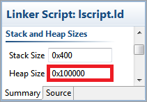

- Copy the source code files into the src directory
- Make sure you uncomment the the required carrier vendor and CPU architecture from the app_config.h (or config.h) header file.
- Example for choosing the Altera carrier in the app_config.h header file:
//#define XILINX
#define ALTERA
- If there are multiple folders present in in the src one, include all the paths of the folders: go to the settings of the project and in the C/C++ Build → Settings → Tool Settings → gcc compiler → Directories section and add the paths of all the folders.
- The SDK should automatically build the projects and the Console window will display the result of the build. If the build is not done automatically select the Project → Build Automatically menu option.
- At this point the software project setup is complete, the FPGA can be programmed and the software can be downloaded into the system. You can program the FPGA by clicking on Xilinx Tools → Program FPGA
- After the FPGA was programmed, we need to create a new Run configuration, by selecting Run → Run Configurations…, in the Run Configuration windows select the Xilinx C/C++ application (System Debugger) and click at the New Configuration button at the upper left corner.

- If your target carrier has a Zync SoC, make sure, that you specify the Initialization file, and select the Run ps7_init and Run ps7_post_config options.

- At the Application tab define your current project name and application executable. (.elf)

- The output of the example program can be viewed in the SDK console by enabling the Connect STDIO Console option and setting the baud rate of the UART port to 115200.

- As an alternative a UART terminal can be used to capture the output of the example program. The number of used UART port depends on the computer's configuration. The following settings must be used in the UART terminal:
- Baud Rate: 115200bps
- Data: 8 bit
- Parity: None
- Stop bits: 1 bit
- Flow Control: none
- When the run configuration is done, the software can be started by clicking the Run button.
- Your new bare metal application should run
Console Commands Driver
The Console Commands Driver is optional for the project. It was created in addition to the AD9361 driver to control the part using some console commands.
AD9361 Reference Project Serial Commands
The following commands were implemented for controlling the AD9361:
| Command | Description |
|---|---|
| help? | Displays all available commands. |
| register? | Gets the specified register value. |
| tx_lo_freq? | Gets current TX LO frequency [MHz]. |
| tx_lo_freq= | Sets the TX LO frequency [MHz]. |
| tx_samp_freq? | Gets current TX sampling frequency [Hz]. |
| tx_samp_freq= | Sets the TX sampling frequency [Hz]. |
| tx_rf_bandwidth? | Gets current TX RF bandwidth [Hz]. |
| tx_rf_bandwidth= | Sets the TX RF bandwidth [Hz]. |
| tx1_attenuation? | Gets current TX1 attenuation [mdB]. |
| tx1_attenuation= | Sets the TX1 attenuation [mdB]. |
| tx2_attenuation? | Gets current TX2 attenuation [mdB]. |
| tx2_attenuation= | Sets the TX2 attenuation [mdB]. |
| tx_fir_en? | Gets current TX FIR state. |
| tx_fir_en= | Sets the TX FIR state. |
| rx_lo_freq? | Gets current RX LO frequency [MHz]. |
| rx_lo_freq= | Sets the RX LO frequency [MHz]. |
| rx_samp_freq? | Gets current RX sampling frequency [Hz]. |
| rx_samp_freq= | Sets the RX sampling frequency [Hz]. |
| rx_rf_bandwidth? | Gets current RX RF bandwidth [Hz]. |
| rx_rf_bandwidth= | Sets the RX RF bandwidth [Hz]. |
| rx1_gc_mode? | Gets current RX1 GC mode. |
| rx1_gc_mode= | Sets the RX1 GC mode. |
| rx2_gc_mode? | Gets current RX2 GC mode. |
| rx2_gc_mode= | Sets the RX2 GC mode. |
| rx1_rf_gain? | Gets current RX1 RF gain. |
| rx1_rf_gain= | Sets the RX1 RF gain. |
| rx2_rf_gain? | Gets current RX2 RF gain. |
| rx2_rf_gain= | Sets the RX2 RF gain. |
| rx_fir_en? | Gets current RX FIR state. |
| rx_fir_en= | Sets the RX FIR state. |
| dds_tx1_f1_freq? | Gets current DDS TX1 F1 frequency [MHz]. |
| dds_tx1_f1_freq= | Sets the DDS TX1 F1 frequency [MHz]. |
| dds_tx1_f2_freq? | Gets current DDS TX1 F2 frequency [MHz]. |
| dds_tx1_f2_freq= | Sets the DDS TX1 F2 frequency [MHz]. |
| dds_tx1_f1_phase? | Gets current DDS TX1 F1 phase [degrees]. |
| dds_tx1_f1_phase= | Sets the DDS TX1 F1 phase [degrees]. |
| dds_tx1_f2_phase? | Gets current DDS TX1 F2 phase [degrees]. |
| dds_tx1_f2_phase= | Sets the DDS TX1 F2 phase [degrees]. |
| dds_tx1_f1_scale? | Gets current DDS TX1 F1 scale. |
| dds_tx1_f1_scale= | Sets the DDS TX1 F1 scale. |
| dds_tx1_f2_scale? | Gets current DDS TX1 F2 scale. |
| dds_tx1_f2_scale= | Sets the DDS TX1 F2 scale. |
| dds_tx2_f1_freq? | Gets current DDS TX2 F1 frequency [MHz]. |
| dds_tx2_f1_freq= | Sets the DDS TX2 F1 frequency [MHz]. |
| dds_tx2_f2_freq? | Gets current DDS TX2 F2 frequency [MHz]. |
| dds_tx2_f2_freq= | Sets the DDS TX2 F2 frequency [MHz]. |
| dds_tx2_f1_phase? | Gets current DDS TX2 F1 phase [degrees]. |
| dds_tx2_f1_phase= | Sets the DDS TX2 F1 phase [degrees]. |
| dds_tx2_f2_phase? | Gets current DDS TX2 F2 phase [degrees]. |
| dds_tx2_f2_phase= | Sets the DDS TX2 F2 phase [degrees]. |
| dds_tx2_f1_scale? | Gets current DDS TX2 F1 scale. |
| dds_tx2_f1_scale= | Sets the DDS TX2 F1 scale. |
| dds_tx2_f2_scale? | Gets current DDS TX2 F2 scale. |
| dds_tx2_f2_scale= | Sets the DDS TX2 F2 scale. |
Executing a Command Example
Commands can be executed using a serial terminal connected to the UART peripheral of the development board.
The following image shows an example of how the TX LO frequency can be set to 2.4 GHz using the corresponding command.

Download no-OS
The source code of the no-OS software and the scripts can be downloaded from the Analog Devices github.
- AD9361 Example project no-OS/tree/master/projects/ad9361
- AD9361 Generic Driver no-OS/tree/master/drivers/rf-transceiver/ad9361
- Linux Makefile no-OS/tree/master/projects/ad9361/src/Makefile.linux
More Information
resources/eval/user-guides/ad-fmcomms2-ebz/software/no-os-setup.txt · Last modified: 01 Apr 2016 16:31 by Dragos Bogdan