Testing the AD-FMComms1-EBZ Board
Analog Devices uses six designations to inform our customers where a semiconductor product is in its life cycle. From emerging innovations to products which have been in production for twenty years, we understand that insight into life cycle status is important. Device life cycles are tracked on their individual product pages on analog.com, and should always be consulted before making any design decisions.
This particular articl/edocument/design has been retired or deprecated, which means it is no longer maintained or actively updated, even though the devices themselves may be Recommended for New Designs or in Production. This page is here for historical/reference purposes only.
Testing this board, is based on data/algorithms which can be found at:
Required Software
ml605_restoring_CF_flash_contents_AD-FMCOMMS1-EBZ.zip (CF Card filesystem contents)
FMCOMMS1_TEST_ACE.TAR.BZ2
mkdosfs.zip – utility used to format the CF Card with an appropriate FAT16 filesystem.
Required Hardware
Xilinx ML605
1GB or 2GB CompactFlash card (Sandisk Ulra II or similar)
AD-FMCOMMS1-EBZ FMC Board.
Rohde & Schwarz FSEA30, FSEA20, FSEB20, FSEB30, or similar. (These are not avalible new anymore, but can be purchased or rented from your
-
HF SMA Cables, Adaptors, etc.
Software Installs
Hardware Setup
- Connect the ML605 power and Ethernet cables.
- Set SACE MODE switches (S1) to
SYSACE MODE: ON
CFGAddr2: OFF
CFGAddr1: ON
CFGAddr0: OFF
Testing
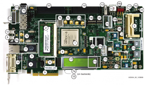
Testing the AD-FMComms1-EBZ board uses the ML605 board from Xilinx. You should be familiar with a few of the connectors as switches on the board:

Connect the AD-FMCOMMS1-EBZ FMC board to the ML605, on the LPC FMC connector (20).
Turn on the power switch on the ML605 board (18A)
Wait ~11 seconds. The DS1 System ACE Status LED should be blinking. This indicates that the ACE file in the CF card is being loaded.
Wait ~10 seconds more. The blue light on the AD-FMComms1-EBZ should start blinking, indicating that the card is being initialized.
Wait ~10 seconds more. The LCD should display the IP number of the board, and the line “XCOMM LPC”, this indicates that the Linux kernel booted on the Microblaze is properly configured, and found all the devices on the card.
In total, this step should take ~30 seconds.
Observe LCD Display (17f).

On the Linux development system open dactune application
Under the Setting TAB
IP NETWORK: Enter target IP Address (same as printed on the display)
IEEE 488 / IEC625 GPIB Interface: Enter GPIB Address (FSEA instrument settings specific)
IEEE 488 / IEC625 GPIB Interface: Enter GPIB tty (use dmesg on your Linux box after you plugged in the Prologix GPIB-
USB Interface, typically /dev/ttyUSB0 or /dev/ttyUSB1)
IEEE 488 / IEC625 GPIB Interface: You may want to enable the calibrate checkbox as well.
Files: Set path to CalPlan2.ini located within the dactune source directory.
Under the DAC TAB
In case a programmed board is detected a dialog will be displayed and you are prompted to enter the PCB serial number.
Observe the LCD display: Make sure that the Serial number printed on Line2 reflects the value previously entered.
Now click on the big AutoTunePlan button and wait.
You will be prompted to connect XCOMM DAC out to the Spectrum Analyzer RF Input.
Do so and press OK.
Wait
Now you will be prompted to connect XCOMM DAC out to ADC Input using a straight SMA to SMA Male cable.
Do so and press OK.
Wait (less) after a few seconds the calibration finished (please observe message box for an error)
Click CONNECT again to disconnect the board.
Repeat steps 6..18 for additional boards.
In the dactune source directory there should exist a results.SN####.tar file for every tested board.

