


This version (16 Dec 2015 23:05) was approved by Robin Getz.The Previously approved version (08 Jan 2015 23:27) is available.
Table of Contents
FMComms Math
This is still in a draft stage. If you have any comments, please comment on the forums
In a traditional radio transmit architecture, a baseband signal (voice or data), is modulated to an intermediate frequency (IF) and then modulated again to the transmit radio frequency (RF) and on the receive side, the opposite happened, from RF to IF to baseband. This was done since inexpensive up-converting modulators/down-converting demodulators only provide adequate performance over roughly one decade of frequency conversion, so it is often necessary to execute the complete up-conversion in two or more frequency hops.
This is no longer the case using modern modulator devices, such as the ADL5375 or ADL5380. These provide up to 200MHz of baseband bandwidth, (fig 64 in the ADL5375 datasheet and fig 6 of ADL5380) and allow up/down conversion from 400 to 6000MHz. In order to use these types of devices, a complex (real and imaginary, not difficult) modulation/demodulation scheme must be used.
Like most mathematical derivations, we will ignore the real world imperfections, and these will be discussed at near the end.
Complex modulation
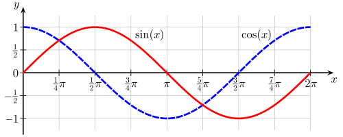
Complex modulation is not difficult to understand at the very basics. We take have 2 baseband signals - for now, I and Q, where one is sine, and the other is cosine.
;
Since we know through trig identities (plus Wikipedia says it's true) that:
then:
;
these are the two signals coming out of the DAC - two sine waves, phase offset from each other, which we call I and Q, like the picture. Whether we call them both sine, or sine and cosine, is immaterial. Sometimes both are used, whatever is easier for the (a) math, or (b) conceptual understanding, and many people will swap back and forth depending on what is being discussed at that time.

Most modern modulators, like the ADL5375 will take the:
- I multiply it by a LO (local oscillator),
- Q multiply it by a LO (local oscillator) shifted by 90 degrees (which is the equivalent of cos())
- add the resulting waveforms together.
;
;
And a little Summation Trig Identities, turns into:
And you get single tone, which is multiplied by the carrier.
You can derive the same using Euler's Formulas,
;
but we end up with the same thing -- a single tone on the RF output by taking three tones (I, Q, and LO) and multiplying and adding them.
Modulation
Starting to modulating signal, just from an amplitude perspective:
;
We still have our carrier:
;
will have the resulting:
;
That gives an output of:
This doesn't really match with Trig Identities, and it's easier to use easier (and by that I mean possible) to use Euler's Formulas
;
therefore:
If we expand this, we get:
and then:
we can re-arrange this as:
and then:
If this is due to amplitude mismatch, this creates something (an image) on the other side of the local oscillator.
resources/eval/user-guides/ad-fmcomms1-ebz/math.txt · Last modified: 16 Dec 2015 23:04 by Robin Getz