This is an old revision of the document!
Dynamometer Drive System
Features
Two BLDC motors connected in a dyno setup
Electronically adjustable load – the load value is set using the onboard buttons + LCD
Programmable step and ramp load changes
Measurement and display of load motor phase currents
Measurement and display of load motor speed
External control using Analog Discovery
Block Diagram
Key Parts
| Power |
| ADuM5000 | isoPower® integrated isolated dc-to-dc converter |
| ADP3335 | HIGH ACCURACY ULTRALOW QUIESCENT CURRENT, 500 mA, ANYCAP® LOW DROPOUT |
| Isolation |
| ADUM3223 | 3 KV RMS ISOLATED PRECISION HALF-BRIDGE DRIVER, 4 A OUTPUT |
User Guide
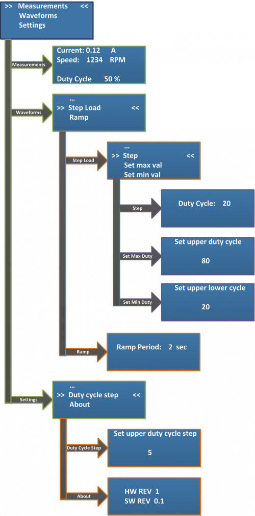
The system is equipped with an LCD which displays information about the state of the load such and together with the 3 push buttons placed below it can be used to display and configure different system parameters. The +/- buttons are used to navigate through the system's menu and to change different system parameters, while the Enter button is used to confirm parameter changes or to enter / exit the menu screens.
| Menu diagram | Menu description |
 | Main menu is displayed at power up.
|
| The measurement menu displays RMS phase currents and motor speed. The load can be adjusted by pressing the “+” or “-” buttons. In order to go back to the main menu press “Enter”. |
Waveforms menu. Select ramp or step load.
In order to go back select “…” and press “Enter”
|
Step load menu. Select “Step” to start toggling the load.
|
Press “+” or “-” to toggle between the preset step values.
In order to go back press “Enter”
|
Set maximum duty cycle.
In order to go back press “Enter”
|
Set minimum duty cycle.
In order to go back press “Enter”
|
Ramp load menu. Press “+” or “-” to change ramp period.
In order to go back press “Enter”
|
Settings menu.
In order to go back select “…” and press “Enter”
|
Change duty cycle step.
|
About.
|
The system needs a 5V 500mA power supply. The power connector is a 2.1 X 5.5MM jack with the center pin positive(+)
 This version (21 Feb 2014 15:02) was approved by Lucian Sin.The Previously approved version (11 Feb 2014 08:37) is available.