Analog Devices uses six designations to inform our customers where a semiconductor product is in its life cycle. From emerging innovations to products which have been in production for twenty years, we understand that insight into life cycle status is important. Device life cycles are tracked on their individual product pages on analog.com, and should always be consulted before making any design decisions.
This particular articl/edocument/design has been retired or deprecated, which means it is no longer maintained or actively updated, even though the devices themselves may be Recommended for New Designs or in Production. This page is here for historical/reference purposes only.
ezLINX™ iCoupler® Isolated Interface Development Environment Homepage
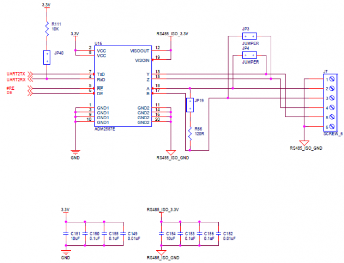
The Isolated RS-485 and RS-422 port is implemented using the ADM2587E Signal and Power isolated RS-485 transceiver. The ADM2587E connects to UART2 of the ADSP-BF548 and is capable of functioning at data rates of up to 500kbit/s. Figure 1 below shows a circuit diagram of the implementation of the ADM2587E on the ezLINX hardware.

The RS-485 Node can be configured using jumpers JP3, JP4, JP19 and JP40. To configure the node as a half-duplex RS-485 node, connect JP3 and JP4. When JP3 is fitted, it will connect B to Z, and when JP4 is fitted it will connect A to Y. When JP3 and JP4 are removed, the node will be configured as a full duplex RS-485 node or as an RS-422 node. When JP19 is fitted, the A and B pins will be terminated with 120Ω. If termination is not required, remove JP19. When JP40 is connected a pull-up resistor on the RxD pin of 10kΩ will be connected. This jumper should be connected when using the ADM2587E in half-duplex mode. The relevant jumper configurations are shown below. A list of jumper configurations for all the interfaces on ezLINX can be found here.
| Full-Duplex | Half-Duplex | 120Ω termination | |
|---|---|---|---|
| JP3 | Open | Connected | N / A |
| JP4 | Open | Connected | N / A |
| JP19 | N / A | N / A | Connected |
| JP40 | N / A | Connected | N / A |
The 3.3V supply is connected to VCC (pin 2 and 8) to power the isoPower isolated Power supply and iCoupler signal isolation of the ADM2587E. This generates an isolated 3.3V on the Visoout pin (pin 12) of the ADM2587E and is connected to the Visoin pin (pin 19).
A six pin screw terminal connector, J7 is used for easy access to the A(Pin 2), B(Pin 3), Z(Pin 4), Y(Pin 5) and RS-485_ISO_GND(Pin 1 and 6) connections.
Application note AN-960 provides more information on circuit implementation of RS-485 and RS-422 applications.