 This version (01 Apr 2022 04:05) was approved by Marymae Hermoso.The Previously approved version (29 Mar 2022 11:00) is available.
This is an old revision of the document!
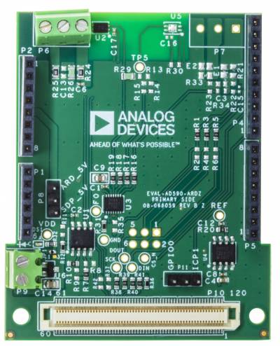
This user guide describes the EVAL-AD590-ARDZ evaluation board hardware and software and includes detailed schematics and PCB layout artwork. This evaluation board is simple, easy-to-use platform which allows direct evaluation of the AD590 analog temperature sensor.
The AD590 is a 2-terminal integrated circuit temperature transducer that produces an output current proportional to absolute temperature. Requiring supply voltages between 4V and 30V, the device acts as a high impedance, constant current regulator passing 1μA/K. Laser trimming of the chip’s thin-film resistors is used to calibrate the device to 298.2μA output at 298.2K (25°C).
When using the AD590 evaluation board, in addition to this user guide, the user should also consult the AD590 datasheet (available at the Analog Devices, Inc., website, www.analog.com).


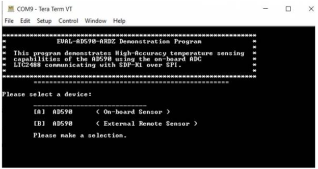
The software is designed to be simple and straight forward to use. Select which sensor you would like to use, whether you want to use the internal sensor or a remote one and then simply enter a number corresponding to the required command and follow the on-screen prompts. Refer to software manual EVAL-AD590-ARDZ Mbed Example [Analog Devices Wiki] for more detailed information.
